5 - 35
ELECTRIC CIRCUIT
CASE TRAINING CENTER
AUGUST 2000
Swing brake
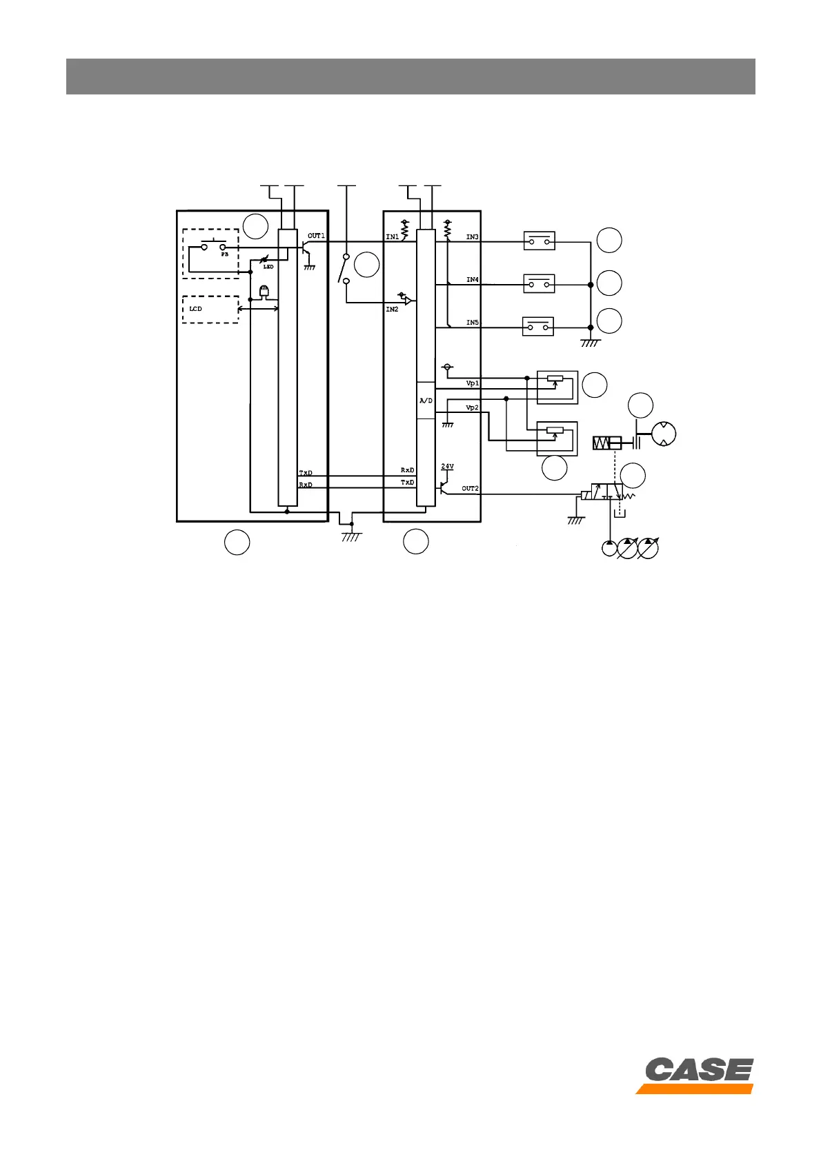
1) Circuit configuration
CS00F503
1. Instrument panel
2. Swing brake switch
3. Starter motor switch
4. Main electronic control box
5. Swing pilot pressure switch
6. Pilot pressure switch
7. Travel pressure switch
8. Pressure detector P1
9. Pressure detector P2
10. Swing brake
11. Swing brake solenoid valve
2) Swing brake control operation
When the swing brake switch (2) is operated, the red LED comes on and the swing brake locks.
When the swing brake switch is operated again, the red LED goes out, the swing brake unlocks and changes to
automatic control (see paragraph 4).
While the swing is locked, the transistor OUT 2 output is activated and the swing brake (10) is locked.
The swing brake remains in the previous state even when the ignition is switched off.
2
1
3
4
5
6
7
8
9
10
11