ELECTRIC CIRCUIT
5 - 36
CASE TRAINING CENTER
AUGUST 2000
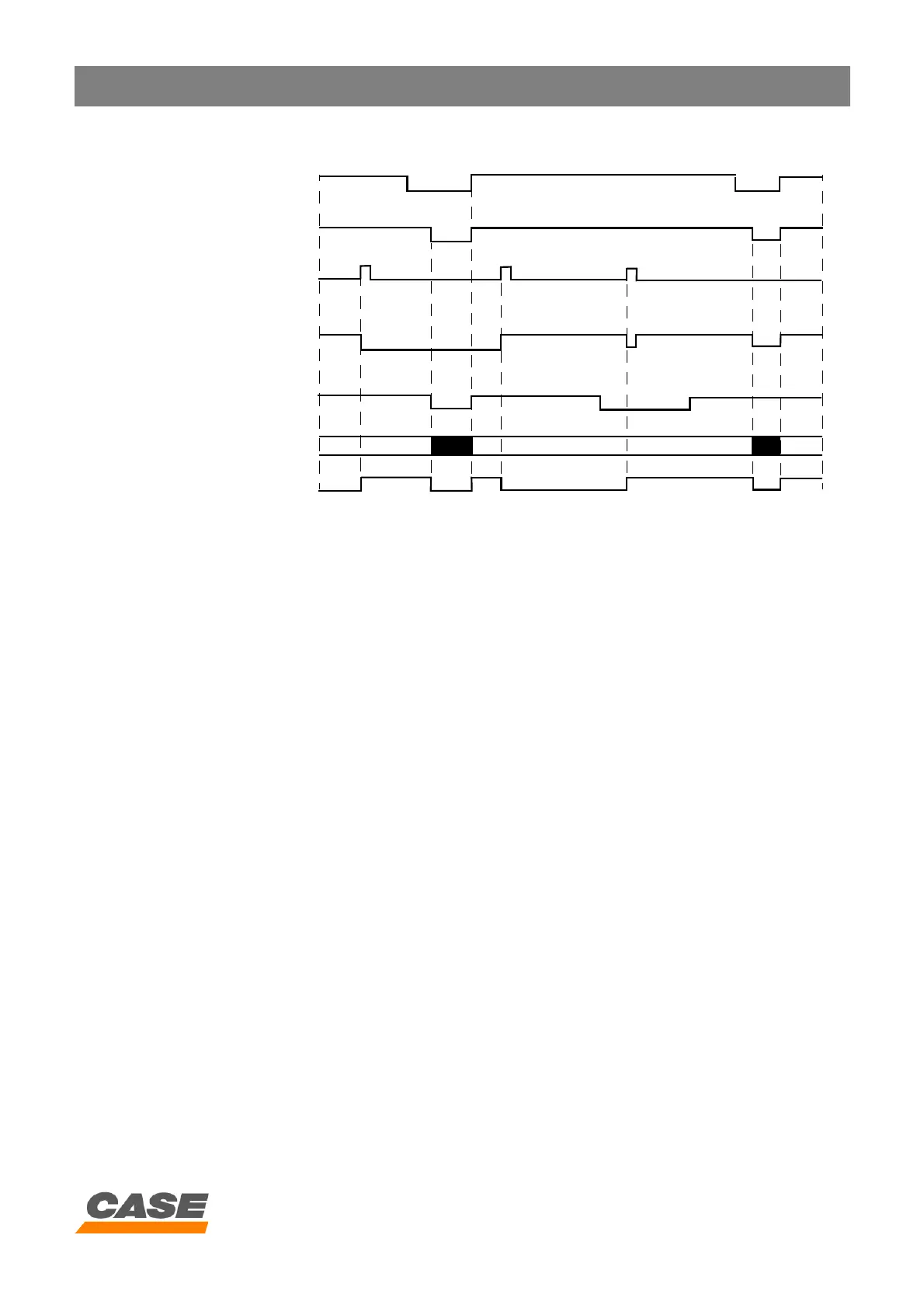
3) Timing diagram
4) Automatic swing brake control
Automatic brake control operates when the swing brake red LED is off.
When the swing and an attachment function are operated simultaneously, the mechanical swing brake is
automatically disengaged. When the operation stops, the mechanical swing brake is automatically activated by
the main electronic control box.
The swing brake is automatically deactivated when:
- The swing pilot pressure switch (5) is activated.
- When the pressure at the pressure detectors P1 (8) or P2 (9) is higher than 150 bar (15 MPa).
The swing brake is automatically activated when:
- The pilot pressure switch (6) is deactivated for more than 5 seconds.
- The starter switch (3) is in the = OFF position.
When the pressure supplied by the pump (P1 or P2) exceeds 150 bar (15 MPa) during one single travel, the
mechanical swing brake is deactivated for 5 seconds, then reactivated.
ON
OFF
24 V
0 V
ON
OFF
5 V (OFF)
0 V (ON)
5 V
0 V
ON
OFF
OFF ON ON OFF ON ON
Supply
Brake
LED
OUT
(N1)
Starter motor
switch
Swing brake switch
Swing pilot
pressure switch