ELECTRIC CIRCUIT
5 - 44
CASE TRAINING CENTER
AUGUST 2000
Fuel level
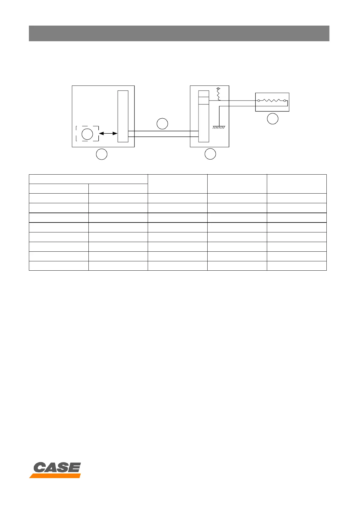
1) Circuit configuration
CM00F009
1. Instrument panel
2. Main electronic control box
3. Fuel level sender
4. Fuel level indicator
5. Series connection
2) Operation
A. The fuel level sender (3) sends a signal to the main electronic control box (2).
B. The main electronic control box (2) calculates the number of bars to be displayed and sends the information to the
fuel level gauge (4) via the series connection (5).
C. When only one bar is displayed on the fuel level gauge (4), the message “LOW FUEL” appears on the instrument
panel control screen (1) and the audible warning device sounds.
Remaining fuel (L)
Fuel level sender
resistor (W)
Input voltage (V) Bars displayed
CX130 CX210
191.1 - 261.6 - 10.0 - 18.1 0.455 - 0.766 8
159.8 - 191.1 232.8 - 261.6 18.1 - 23.9 0.766 - 0.964 7
128.5 - 159.8 190.0 - 232.8 23.9 - 29.6 0.964 - 1.142 6
97.1 - 128.5 147.1 - 190.0 29.6 - 36.5 1.142 - 1.337 5
65.7 - 97.1 104.2 - 147.1 36.5 - 46.3 1.337 - 1.582 4
34.4 - 65.7 51.2 - 104.2 46.3 - 60.8 1.582 - 1.891 3
15.6 - 34.4 25.6 - 51.2 60.8 - 74.7 1.891 - 2.138 2
< 15.6 < 25.6 74.7 - 80.0 2.138 - 2.222 1
4
1
5
2
3