ELECTRIC CIRCUIT
5 - 46
CASE TRAINING CENTER
AUGUST 2000
2) Electronic regulator
CS00F532
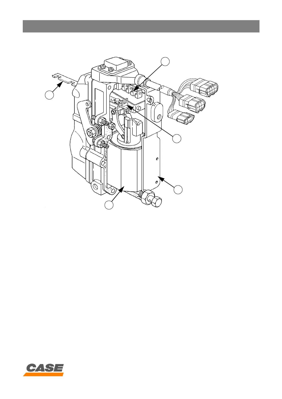
17. Linear motor
18. Rack
19. Linear motor control section
20. Rack position detector
3) Operation
A. To ensure low fuel consumption and optimum productivity, the engine electronic control box (3) memorises the
various work modes (M, S and L) and selects the optimum work mode in accordance with the signal that it receives
from the main electronic control box (4) via the CAN connection (11).
B. The electronic regulator (7) has an input section, a calculating section and a linear motor control section (17).
C. The input section receives the signals coming from the detectors and senders (12) and transmits them after
processing to the calculation section.
D. The calculation section compares the information received with the memorised data, and then transmits a control
signal to the linear motor (17) control section (19).
E. The control section (19) sends a signal to the regulator (7) linear motor (17) to actuate the fuel injection pump (5) rack
control (18).
18
19
20
7
17