6 - 7
HYDRAULIC CIRCUIT
CASE TRAINING CENTER
AUGUST 2000
Description of Operation
Swing Operation, Swing Parking Circuit
When the engine is started and the swing lever is in neutral, the swing brake solenoid valve is turned ON
(24 V input) and the swing parking brake is activated.
When the swing pressure switch is turned ON by operating the lever, output to the swing brake solenoid
valve from the controller is turned OFF and the swing parking brake is released. Thus swing operation is
enabled. When the swing lever is in neutral and attachments such as arm is moved, lateral force is
produced while swinging. In order to prevent the dragging caused by braking, this parking bake is designed
to be released.
Signals from the pressure sensor A1 or A2 enters the controller and at the time when either one reaches
14.7 MPa, the output to swing brake solenoid valve from the controller is turned OFF and the swing parking
brake is released.
In 5 seconds after the swing pressure switch or attachment pressure switch is turned OFF or the delivery
pressure from A1 or A2 is below 14.7 MPa, the solenoid valve is turned ON and the swing parking valve is
activated.
If the swing lock switch is turned ON, even the swing pressure switch or attachment pressure switch is
turned ON, the swing lock switch has the priority and the parking brake remains unreleased. When the
swing lock switch is turned ON and the swing lever is in operation, the swing spool in the main control valve
will be changed over.
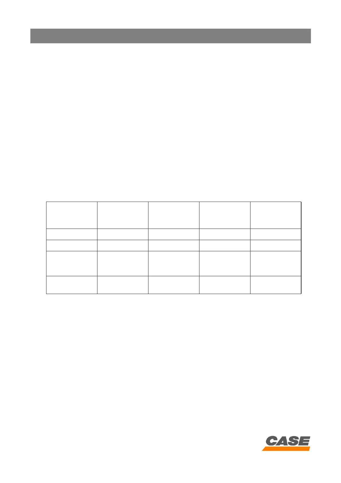
Key switch
Swing pressure
switch
A1 or A2 (MPa)
pressure on
pressure sensor
Swing brake
solenoid valve
Swing motor
mechanical brake
OFF OFF 0 OFF ON
ON OFF 0 ON ON
ON ON
0 or swing
operation
pressure
OFF OFF
ON OFF
14.7 MPa or
more
OFF OFF