— 13 —
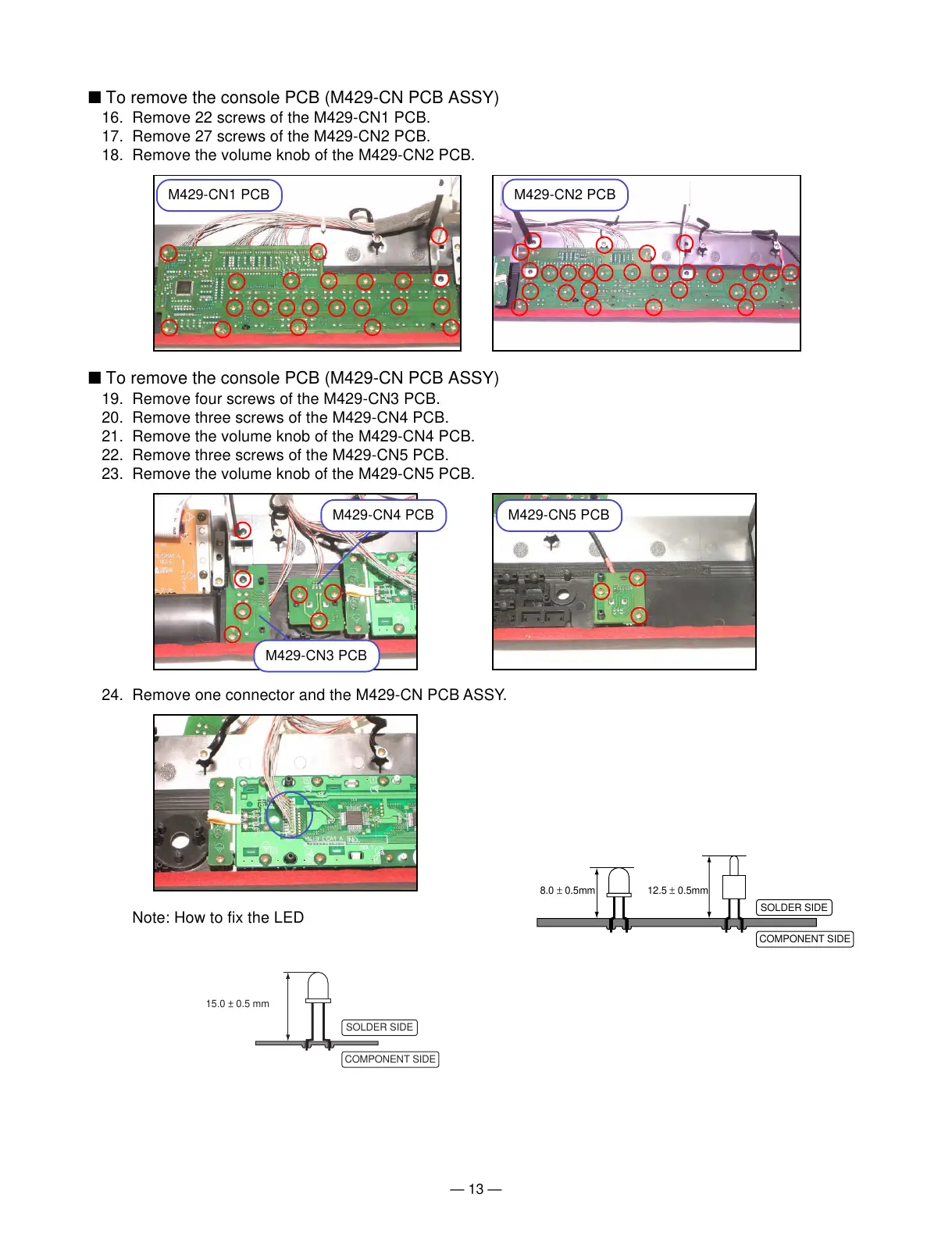
15.0 ± 0.5 mm
SOLDER SIDE
COMPONENT SIDE
8.0 ± 0.5mm 12.5 ± 0.5mm
SOLDER SIDE
COMPONENT SIDE
M429-CN1 PCB
M429-CN2 PCB
M429-CN3 PCB
M429-CN4 PCB M429-CN5 PCB
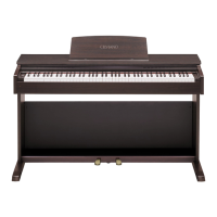
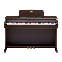
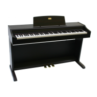
■ To remove the console PCB (M429-CN PCB ASSY)
16. Remove 22 screws of the M429-CN1 PCB.
17. Remove 27 screws of the M429-CN2 PCB.
18. Remove the volume knob of the M429-CN2 PCB.
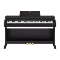
■ To remove the console PCB (M429-CN PCB ASSY)
19. Remove four screws of the M429-CN3 PCB.
20. Remove three screws of the M429-CN4 PCB.
21. Remove the volume knob of the M429-CN4 PCB.
22. Remove three screws of the M429-CN5 PCB.
23. Remove the volume knob of the M429-CN5 PCB.
24. Remove one connector and the M429-CN PCB ASSY.
Note: How to fix the LED