— 68 —
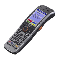
8. Open the inner case assembly as shown to the
right.
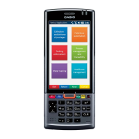
9. Remove Main PC Board assembly after
disconnecting FPC assembled onto LCD Module
from CN4 connector as shown to the right.
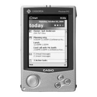
10. Remove the touch panel assembly after
removing screws.
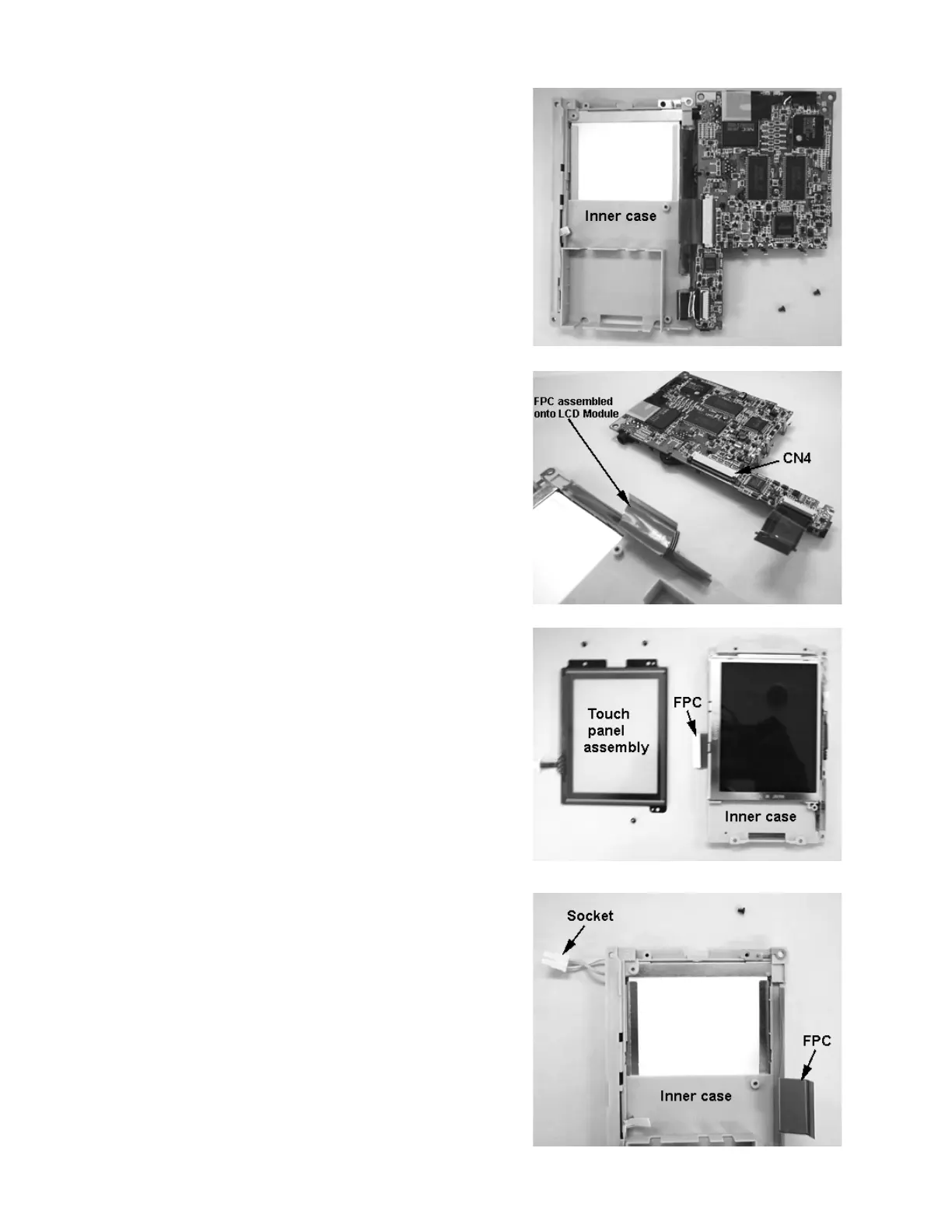
11. Disconnect the socket from CN1 connector
assembled onto the inverter PC Board assembly
as shown to the right.