— 12 —
Pin No. Signal Descriptions I/O
50
P03/SI0/SB1
Key input signal (KI3) In High
51
P02/SO0/SB0
Key input signal (KI2) In High
52
P01/SCK0_
Key input signal (KI1) In High
53 P00/INT4 Key input signal (KI0) In High
54 VSS GND terminal — —
55 XT1 Sub system clock signal (32.768 KHz) In Pulse
56 XT2 Sub system clock signal (32.768 KHz) In Pulse
57 IC GND terminal — —
58 X1 Main system clock signal (4.19 MHz) In Pulse
59 X2 Main system clock signal (4.19 MHz) In Pulse
60 RESET_ Initialize signal In High
61 P143 RAM write enable signal (WE_) Out High
62 P142 RAM chip enable signal (CE_) Out High
63 P141 Journal feed common signal Out Low
64 P140 Receipt feed common signal Out Low
65 P133 RAM data signal (D3) I/O High
66 P132 RAM data signal (D2) I/O High
67 P131 RAM data signal (D1) I/O High
68 P130 RAM data signal (D0) I/O High
69 P123 Key common signal (Kc02) Out Pulse
70 P122 Key common signal (Kc01) Out Pulse
71 P121 Key common signal (Kc00) Out Pulse
72 P120 RAM address signal (A14) Out Low
73 AVSS GND terminal — —
74
P153/AN7
Receipt ON/OFF signal In High
75
P152/AN6
Motor error signal In Low
76
P151/AN5
Pad data signal (PAD2) In High
77
P150/AN4
Pad data signal (PAD1) In High
78 AN3 GND terminal — —
79 AN2 Battery voltage detection terminal In
0 ~ 4.5V
80 AN1 Drawer sensor signal In Low
PW-on
level
To Printer
To CPU
Note:The "PW-ON level" is measured under following conditions.
(1) Mode switch is REG position.
(2) The display is the time.
(3) Receipt switch is ON position.
(4) PAD1 and PAD2 are both open.
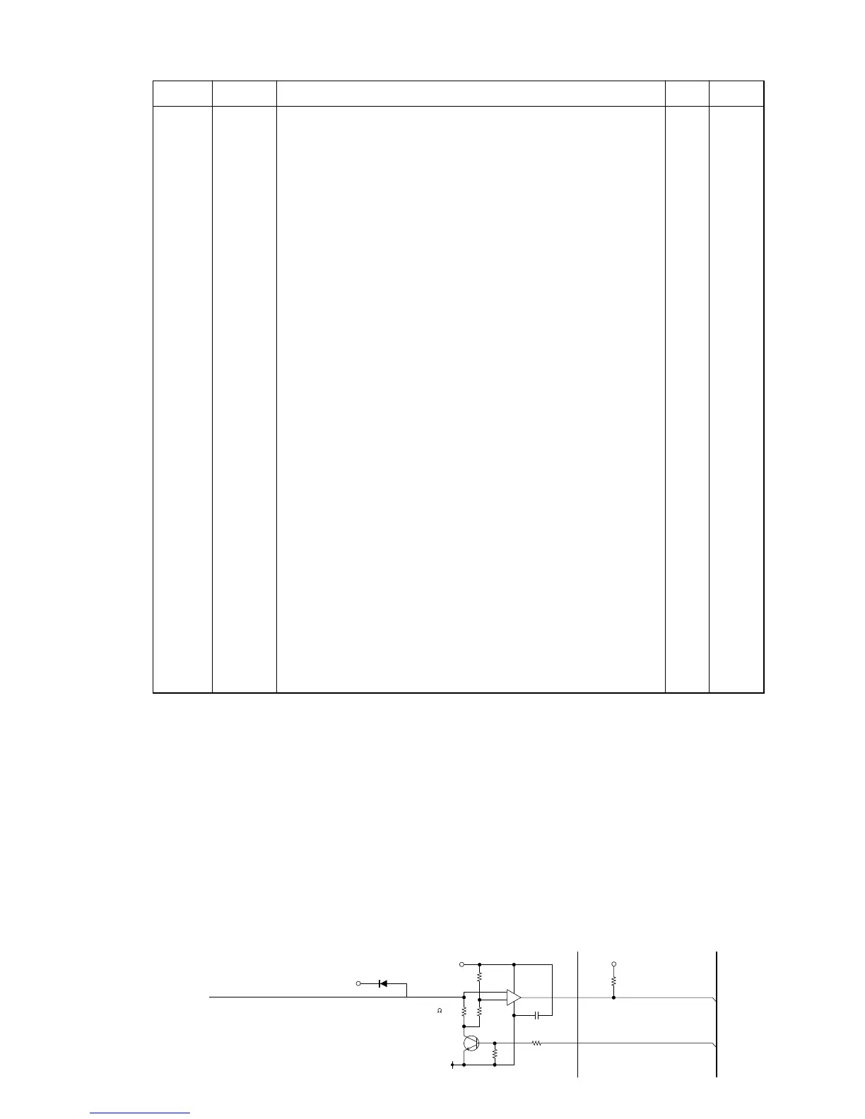
6-3. Motor error detection circuit
When CPU output motor signal, transistor Q8 becomes on and the voltage level at "A" point becomes
GND. Then, paper feeding motor rotate. Normally, pin No. 1 of IC4 appears low signal.
IC4 detects differential voltage between pin No. 2 and 3.
In case pin No. 3 is higher than No. 2, output (pin No. 1) signal is high.
If motor happens over load (paper jam etc.), over load current (250mA) runs resistor R9. So " A" point
voltage level becomes high.
Then IC4 outputs high signal and then CPU knows motor error occured.
Whe the CPU receives "Motor error signal" CPU stops motor signal.
R10
VP
D35
1SR-35-100A
VP
22K
(±2%)
1K
1
BA10393
(±2%)
TFC103
R9
R6
8
3
2
+
3.9 (R50X)
–
Q8
GNDP
10K
R11
2SD1853
1.5K
R26
10K
VCC
R37
MOTOR ERROR
MOTOR
IC4
C10

 Loading...