— 11 —
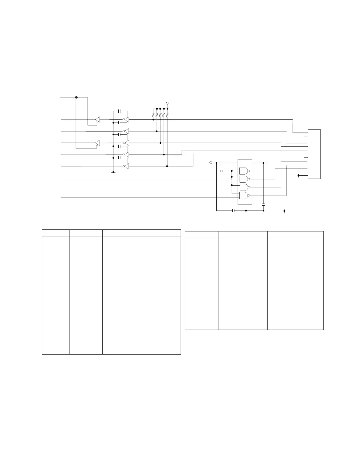
2. On line circuit (RS-232C)
The on line port (RS-232C) is controlled by the USART µPD71051 and
supported only asynchronous communication.
Pin description of UPD71051C
Pin No. Signal Description
1,2,5~8, D0~D7 Data bus
27,28
3 RxDATA Receive data input
9 TxCLK Transmitter clock input
10 WR Write signal
11 CS Chip select signal Input
12 C/D Control or data change
13 RD Read signal
14 RxRDY Receive ready output
15 TxRDY Transmittor ready output
16 SYNC/BRK Syncronization/Break (Not used)
17 CTS Clear to send signal input
18 TxEMP Transmitter empty
19 TxDATA Transmit data output
20 CLK Clock input
21 RESET Reset input
22 DSR Data set ready signal input
23 RTS Request to send signal output
24 DTR Data terminal ready signal output
25 RxCLK Receiver clock input
26 VDD VCC(+5V) terminal
Pin description of on line connector
Pin No. Signal Description
1 SG Signal ground
2 NC Non connection
3 ER Equipment ready
4 SD Send data
5 RTS Request to send
6 NC Non connection
7 RD Receive data
8 CTS Crear to send
9 CD Carrier detect
10 DR Data ready
11 NC No connection
12 NC No connection
13 CI Calling indicator
13
12
11
10
9
8
7
6
5
4
3
2
1
CI
NC
NC
DSR
CD
CTS
RXD
NC
RTS
TXD
DTR
NC
GND
To ON-LINE
RA2
R21
GND
V-
C12
C13
1
3
6
8
11
7
14
2
4
5
9
10
12
13
Vcc
IC8
IC3
C14
C16
C15
C17
C18
3
2
1
6
5
4
8
9
10
11
12
13
3
2
1
IC6
IC6
IC6
IC6
IC8
9
11
12 8
1
19
GNDGND
GND
V+ V-
GND
GND
RDTM
D4
DSR
D6
CTS
RXD
DTR
RTS
TXD
 Loading...