— 13 —
Input. On a non-multiplexed bus,
these signals are dirctly connectoed to
the low bits of the host address bus.
On a multiplexed address/data bus,
A0/MUX is tied low, A1 is left open,
and A2 is tied to the address latch
enable signal of the host. A1 is
connectoed to an internal pull-up
resistor.
Input/Output. On a non-multiplexed
bus, these signals are used as the
data lines for the device. On a
multiplexed address/data bus,
AD0~AD2 act as the address lines
(latched by ALE) and as the low data
lines for the device. D3~D7 are
always used for data only. These
signals are connected to internal pull-
up resistors.
Signal ground.
An external crystal shoul be connected
to these pins. If an external TTL clock
is used instead, it must be connected
to XTAL1 with a 390 ohms pull-up
resistor, and XTAL2 should be left
floating.
Output. In normal mode, these active
low signals carry the transmit data
information, encoded in pulse format,
from the COM20020 to the media
driver circuitry. When the device is in
backplane mode, the PULSE1 signal
driver is programmable (push/pull or
open-drain), while the PULSE2 signal
provides a clock with frequency of
crystal/4. PULSE1 is connected to a
week internal pull-up resistor in
backplane mode.
Receive input. This signal carries the
receive data information from the line
receiver circuitry to the COM20020.
Transmit Enable output. This signal
used in backplane mode to enable the
line drivers for transmission. The
polarity of the signal is programmable
by grounding the PULSE2 pin. This
option is valid only in backplane mode.
Input. This active low signal issued by
the microcontroller executes a hard-
ware reset. It is used to activate the
internal reset circuitry within the
COM20020.
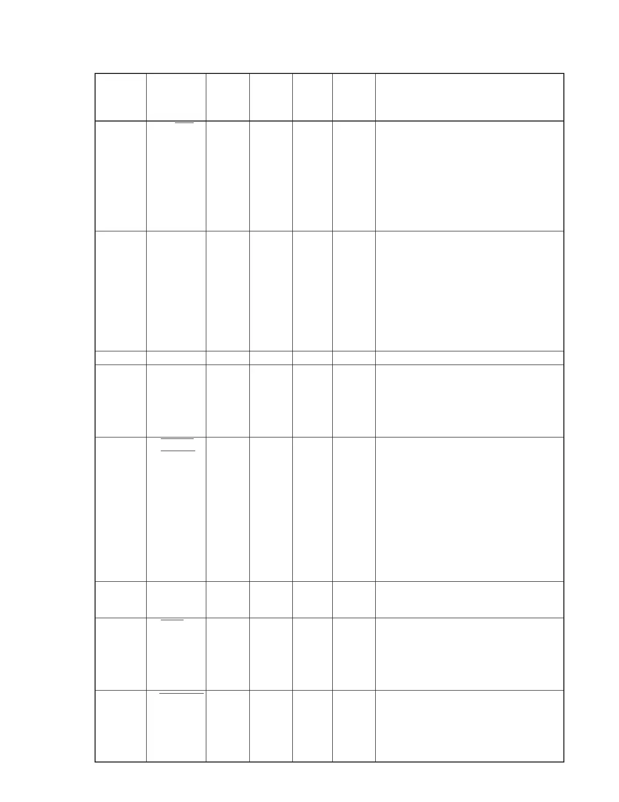
2. COM20020B pin description
Pin No. Name In/Out Status Status Status Description
of OFF of ON of ON
No Token Token
1 A0/MUX In L L Pulse
2 A1 In L L L
3 A2/ALE In L L L
4 AD0 In/Out L Pulse Pulse
5 AD1 In/Out L Pulse Pulse
6 AD2 In/Out L Pulse Pulse
7 D3 In/Out L Pulse Pulse
8 D4 In/Out L Pulse Pulse
9 D5 In/Out L Pulse Pulse
10 D6 In/Out L Pulse Pulse
11 D7 In/Out L Pulse Pulse
12 GND Power GND GND GND
13 XTAL1 In L Pulse Pulse
14 XTAL2 In L Pulse Pulse
15 PULSE1 Out L H Pulse
16 PULSE2 Out L L L
17 RXIN In L H Pulse
18 TXEN Out L L Pulse
19 RESET IN In L H H
 Loading...