– 67 –
IT-G500
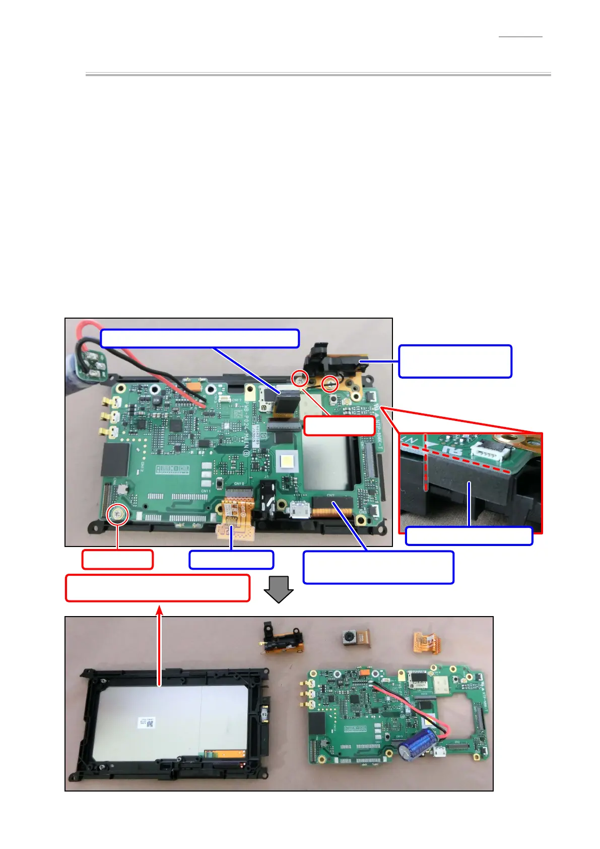
MAIN PCB
WLAN-UNIT/2.4G
(1) Remove the coaxial cable.
(2) Undo 2 screws and remove the WLAN-UNIT/2.4G.
CAMERA MODULE
(3) Release the connector lock and remove 1 FPC.
EXT-UNIT
(4) Release the connector lock and remove 1 FPC.
PCB ASSY/MAIN-PY024
(5) Remove the connector with the spacer (SPACER/LCD CONNECTOR) attached.
NOTE:
Depending on the model, the spacer is not attached.
(6) Peel off the cushion (CUSHION/INNER CASE).
NOTE:
Depending on the model, the cushion is not attached.
(7) Undo 1 screw.
(8) Remove the PCB ASSY/MAIN-PY024.
WLAN-UNIT/2.4G
2 screws (S4)
Connector
+
SPACER/LCD CONNECTOR
EXT-UNIT
CAMERA MODULE
+
SPACER/CAMERA
Screw (S4)
LCD MODULE
Coaxial cable
CUSHION/INNER CASE