— 9 —
AFTER SENSOR ADJUSTMENT
1. AFTER TOUCH SENSOR ADJUSTMENT
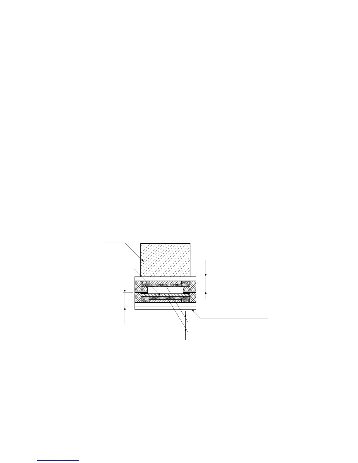
After touch sensor (code number: 1001 2063) is composed of felt, upper and lower electrode
sheets, and both sided adhesive tape. Silicon spacer maintains a certain gap between the upper
and the lower electrodes.
Silver and carbon are printed on upper and lower electrodes. Moreover, a pressure sensor layer
(white) is printed on the lower electrode.
After touch sensors are stuck on the case keyboard and rear position of key guide.
2. Operation principles
1) After pressing key in full stroke, further depression of the key presses the sensor felt.
↓
2) The force of the pressure deforms the upper electrode via the felt.
↓
3) The upper electrode and the lower electrode (with pressure sensor) touch and contact resistance
becomes smaller (isolated before contact).
↓
4) The resistance vary in accordance with contact area and pressure force.
↓
5) The resistance (voltage) variation is converted in digital value by the A/D converter and provided to
the CPU which apply an after touch effect to the sound.
Lower electrode
sheet
Gap
Upper electrode sheet
Both sided adhesive tape
Felt
Pressure
sensitive
layer
Fig.1 Structure of the after touch sensor
3. Replacement of after touch sensor
1) Remove PANEL (R-1) and keys.
2) Remove the tip of after touch sensor from connector on PCB SN1M.
3) Peel after touch sensor off from the CASE (R-2).
4) Clean residue of the adhesive tape from the case using isopropyl alcohol.
5) Stick new after touch sensor with care not to be twisted or crooked.
6) Insert the tip of after touch sensor in connector on PCB SN1M and screw it.
7) Fix the keys.