— 18 —
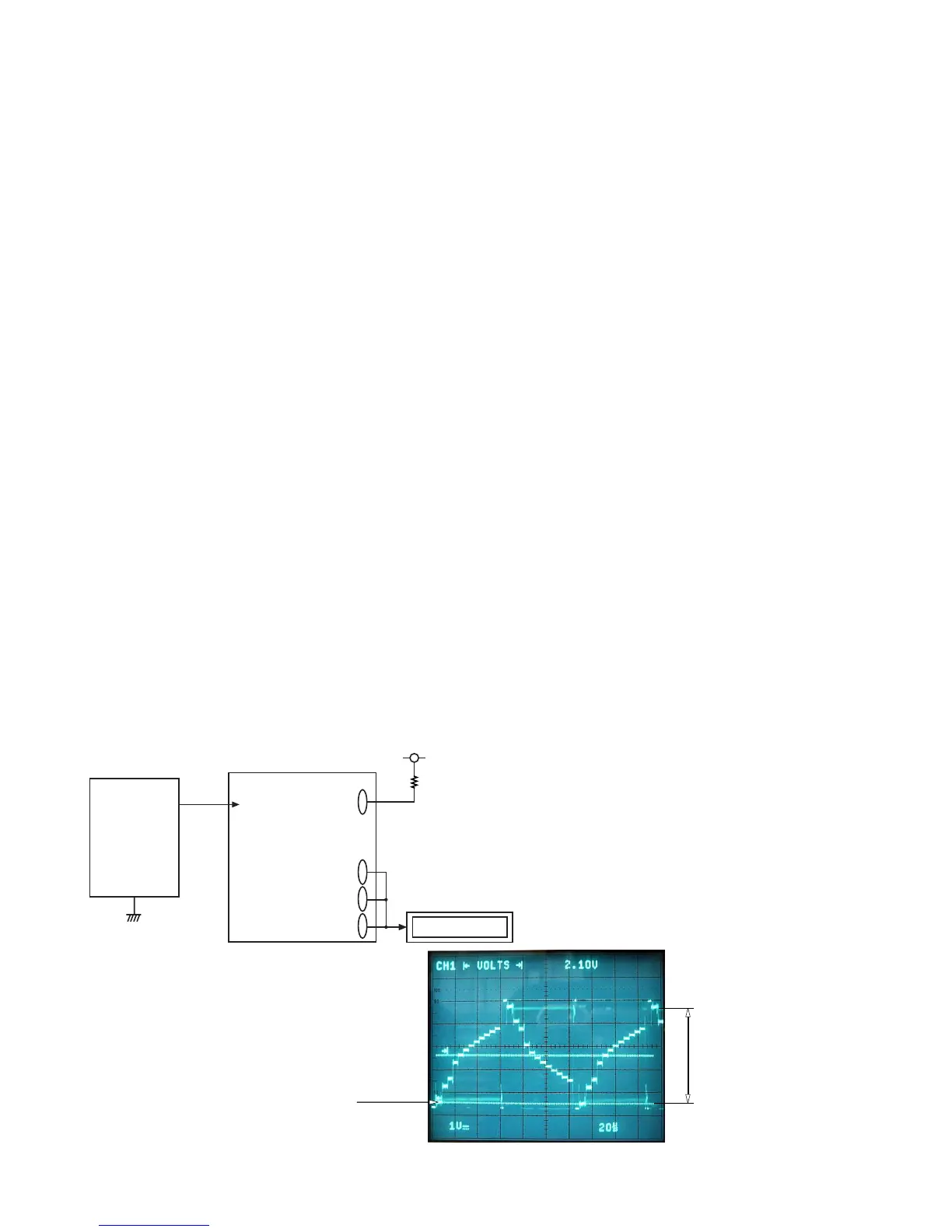
D-PCB
VR(CP320)
VB(CP324)
VG(CP322)
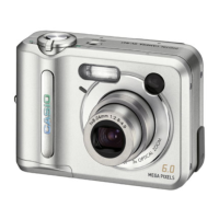
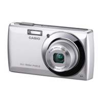
Figure 1
Digital oscilloscope
Killer terminal
(CP308)
QV-2900
VCC5
22KΩ
Power
Supply
5-3. RGB AMP and Sub-Brightness voltage setting adjustment
1. General
Perform the following adjustments in order.
5-3. RGB AMP and Sub-Brightness voltage setting adjustment
5-4. Contrast and Brightness voltage setting adjustment
5-5. TINT setting adjustment
2. Preparation
• AC adaptor or voltage regulator
• Digital oscilloscope
3. Adjustment procedure
(1) Start up Test mode Menu1.
1. Turn POWER on while pressing SHIFT key and MENU button simultaneously
2. Quickly press keys in the order of SHIFT key, SHIFT key and MENU key.
(2) Select / Execute GRAY SCALE (10 step). (NTSC)
(3) Impress the killer terminal (CP308) with VCC5 (CP520) voltage through a 22 kΩ resistance.
(4) Trigger VG waveform (CP322) by FRP (CP300) signal to adjust as noted below.
(5) Adjust RGB-AMP VR (VR302) so that pedestal-pedestal voltage of VG(CP322) signal is 4.70 ± 0.05
Vp-p.
(6) Adjust SUB R BRIGHT VR (VR305) so that potential between VR (CP320) signal’s pedestal and pedestal
is 4.70 ± 0.05 Vp-p.
(7) Adjust SUB B BRIGHT VR (VR304) so that potential between VB (CP324) signal’s pedestal and pedestal
is 4.55 ± 0.05 Vp-p.
3. Notes
• Consecutively, execute 5-4. Contrast and Brightness voltage setting adjustment.
• Make sure that waveforms are not distorted.
4. Connection diagram
Figure 1
pedestal level
4.70 ± 0.05 [Vp-p]
(pedestal – pedestal)
 Loading...