— 14 —
3. Measurement
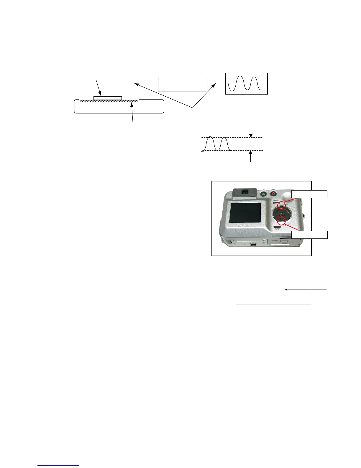
a) Connect S2281-01 to the camera’s LCD monitor (see below).
AC Waveforms appear on the monitor screen of the oscilloscope.
* Change the Rf range of C2719 in case the range does not match.
b) After AC waveforms of the oscilloscope appear, minimize it by pressing the camera’s up/down buttons
(see the picture).
Make sure to visually check if it has been minimized.
Photo diode
S2281-01
LCD
CAMERA
BNC-BNC cable
INPUT OUTPUT
Photo sensor amp
Oscilloscope
Minimize the
ripple components
After it has been minimized, press SET key.
The screen in the right figure appears and the new VCOM
is written (VCOM adjustment is finished.).
OK -> Register Write
VCOM = 0X80
LAST MEMORY SET!
This value is only an example, and differs by products.
Return to the previous display by pressing MENU or PW key.
"Up" button
"Down" button

 Loading...