— 16 —
5. CIRCUIT EXPLANATION
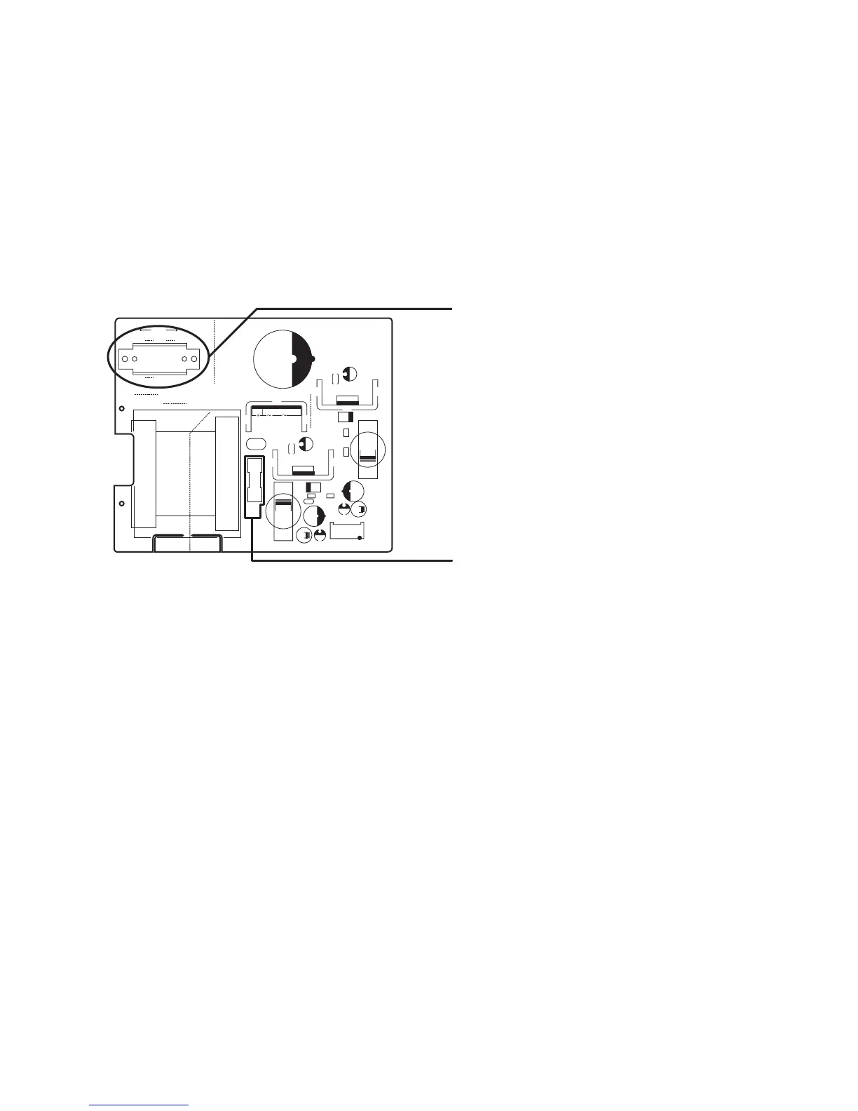
5-1. POWER SUPPLY CIRCUIT
The power supply circuit provides the following voltage for the main circuit.
Output Pin No. 1VC(DC20~31V) For the drawer.
Output Pin No. 2 VCC (DC5V) For the logic circuit power.
Output Pin No. 3 VP (DC8V) For the printer.
Output Pin No. 4 GND
Voltage selector switch (PS-272-U)
Normally, Do not change the voltage position.
230V
SJW3SJW1
SW1
JW4
JW1
R2
F1
T4A
250V
R1
115V
SJW2
JW3
AC2
AC1
PT1
C10
C11
CN1
C3
C2
L2
L4
L1
R3
D3
D2
IC1
IC2
C7
C8
C4
C9
C5
C6
C1
D1
BLACK
PRI SEC
BLK
GND
+8V
+5V
+10V
RED
1
7
17
8
L3
R4
F1: 4A / 250V
 Loading...