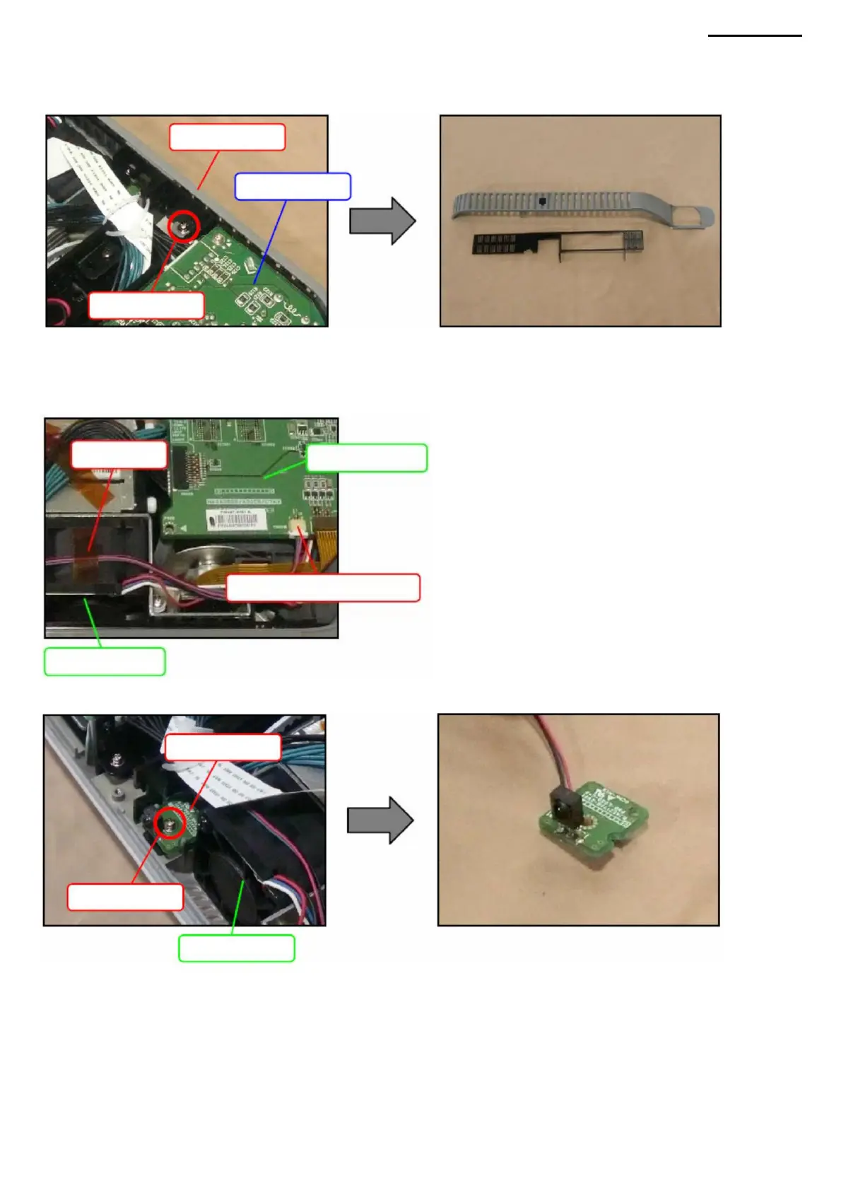
U-2. Remove the tape securing the cables (PWB-5 board) to fan module B.
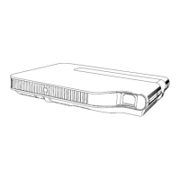
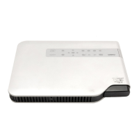
T-1. Unscrew screw (S9) and remove cover F.
XJ-A240/A245
U-1. Disconnect the connector (PWB-5 board) connected to the PWB-1 board.
U-3. Unscrew the screw (S9) and remove the PWB-5 board.
T. COVER F
U. PWB-5 BOARD (IR SENSOR BOARD)
Fan
module B
Connector (PWB-5 board)
-41-
Fan
module B
ACDC module
Cover F
Tape
Screw (S9)
Screw (S9)
Salary PWB-1
Machine Translated by Google
 Loading...