KEQS08
Technical Manual
-3-
Using the unit improperly and performing repairs or modifi cations personally will void the warranty. The producer
declines any responsibility for damages due to inappropriate use of the product and due to any use other than the
use the product was designed for. The producer declines any responsibility for consequential damages except civil
liability for the products.
Every programming and/or every maintenance service should be done by qualifi ed technicians.
1.1 Safety precautions
1 Introduction
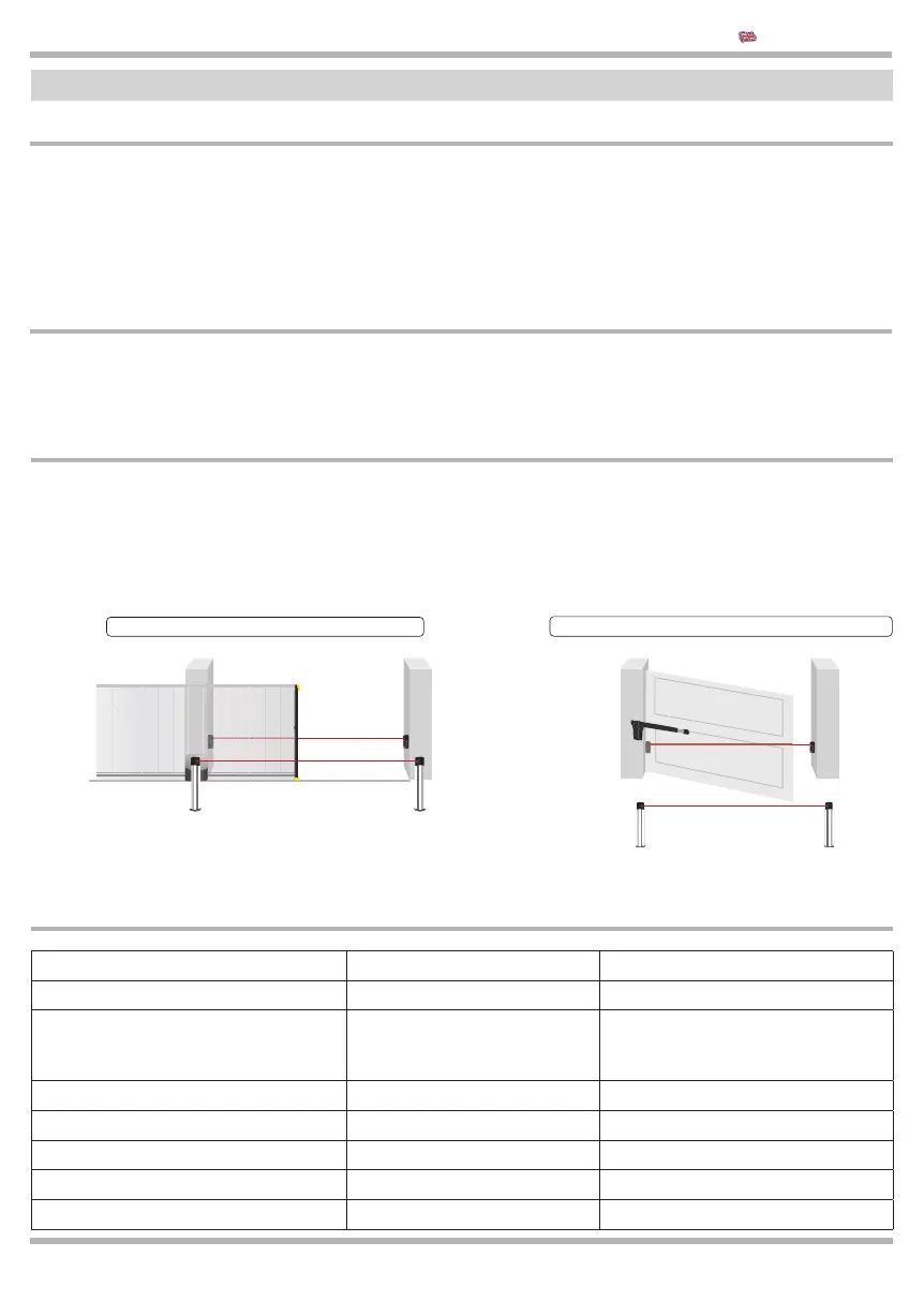
1.3 Type of installation
These two simple diagrams show only one of the possible applications for this control unit. The risks inherent to
the “MACHINE” and the user’s requirements must be analyzed in depth in order to establish how many elements
need to be installed. All photocells have a system of synchronism that makes it possible to eliminate interference
between two pairs of photocells (for other details, see the instructions for the photocells). In the diagram, the pair of
photocells “Photo A” (considered in this control unit) has no eff ect during opening while it causes a total inversion
during closing. “Photo A2” is connected in series to “Photo A”.
Installation for sliding gates
Installations for swing gates
FOTO A
FOTO A2
We recommend to install a STOP switch which stops immediatelly the gate.
The switch has a normally close contact which opens the contact when it is
working. See Par. 2.7
The KEQS08 electronic control unit is used to control the movement of entrances, swinging gateways, rolling
gates and automatic doors. It can be connected to a hydraulic or electromechanical actuator equipped with an
asynchronous, single-phase motor operating at a voltage of 230 Vac.
1.2 Field of application
Dimensions 87 x 150 x 45 mm
Weight 0.6 Kg
MAX power of single motor 1
750
4
HP
W
A
MAX power of signal light 230 Vac 40 W
MAX consumption for dry 2 A
MAX consumption 24 Vac/dc 300 mA
MAX consumption 12 Vdc 50 mA
MAX consumption 12 Vac 1 A
1.4 Technical description
FOTO A
FOTO A2