-4-
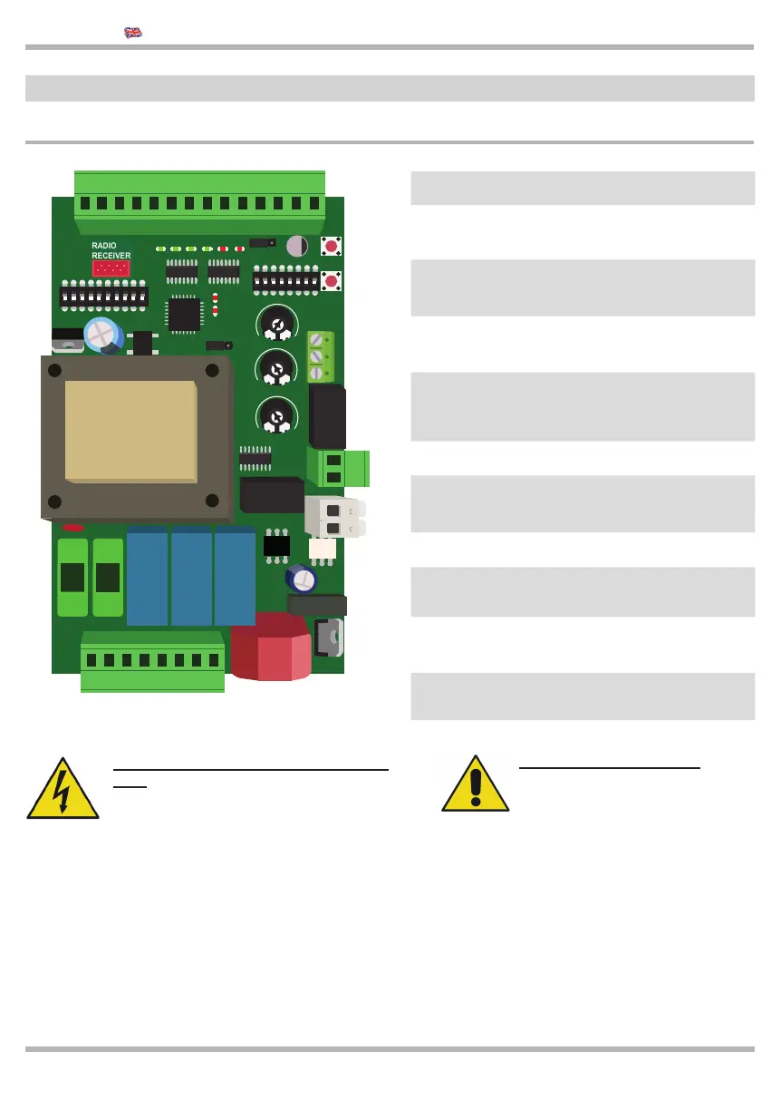
1 2
Control unit power supply 230Vac
3 7
Power supply for 230Vac motor and for
230Vac Signal Light
8 21
Power supply for accessories and inputs and
securities
22 23
Electrical lock,
Power supply of the accessories
24 25
“Dry” contacts for light or photocell TEST
or signal light without fl ashing control card
26 28
Connection of the encoder
JUMPER
AC/DC
Selection of the power supply,
24 Vac output or dc on terminals 18-19-20
JUMPER
JP1
“Death man” function (Par. 3.3)
DIP A Set up of the logic of the control unit
DIP B
Exclusion of the inputs,
activation of Soft-start (gradual start)
Button P
Managing of the remote controlsd, force
adjustment, increase of the pause time
2.1 Diagram of the control unit and electrical connections
2 Installation
Connection of the POWER SUPPLY
LINE 230 Volt Single-phase alternate cur-
rent. The control unit power supply line
must always be protected with a magnetic-
thermal switch or a pair of 5A fuses.
An earth leakage circuit breaker is recom-
mended but not necessary if already avai-
lable in the site if one is already installed
on the plant.
Connection of the MOTOR
Pay attention not to invert
the OPEN and CLOSE poles.
When in doubt as to the correct connection, if
possible, manually position the automation at the
midpoint of its stroke. Be ready to stop the system
using the STOP control!
To be sure that the opening is really “opening”, try
to block the photocells: if the gate begins to close,
the connection is incorrect and the motor OPEN
and CLOSE wires must be inverted.
KEQS08
Technical Manual
20
40
60
80
100
0
2
4
6
8
10
MAX
MIN
2
4
6
8
10
OFF
ON
1
23 4
5
678
9
10
KE
ON
1
23 4
KE
5
67 8
FORZA
TEMPI
CODICI
L1
L2
V.RALLBLOCK
8 9 10 11 12 13 14 15 16 17 18 19 20 21
1 2 3 4 5 6 7
24 25
22 23
26 27 28
F1 - 160mA
F2 - 4A
JP1
DIP A
DIP B
AC / DC