2
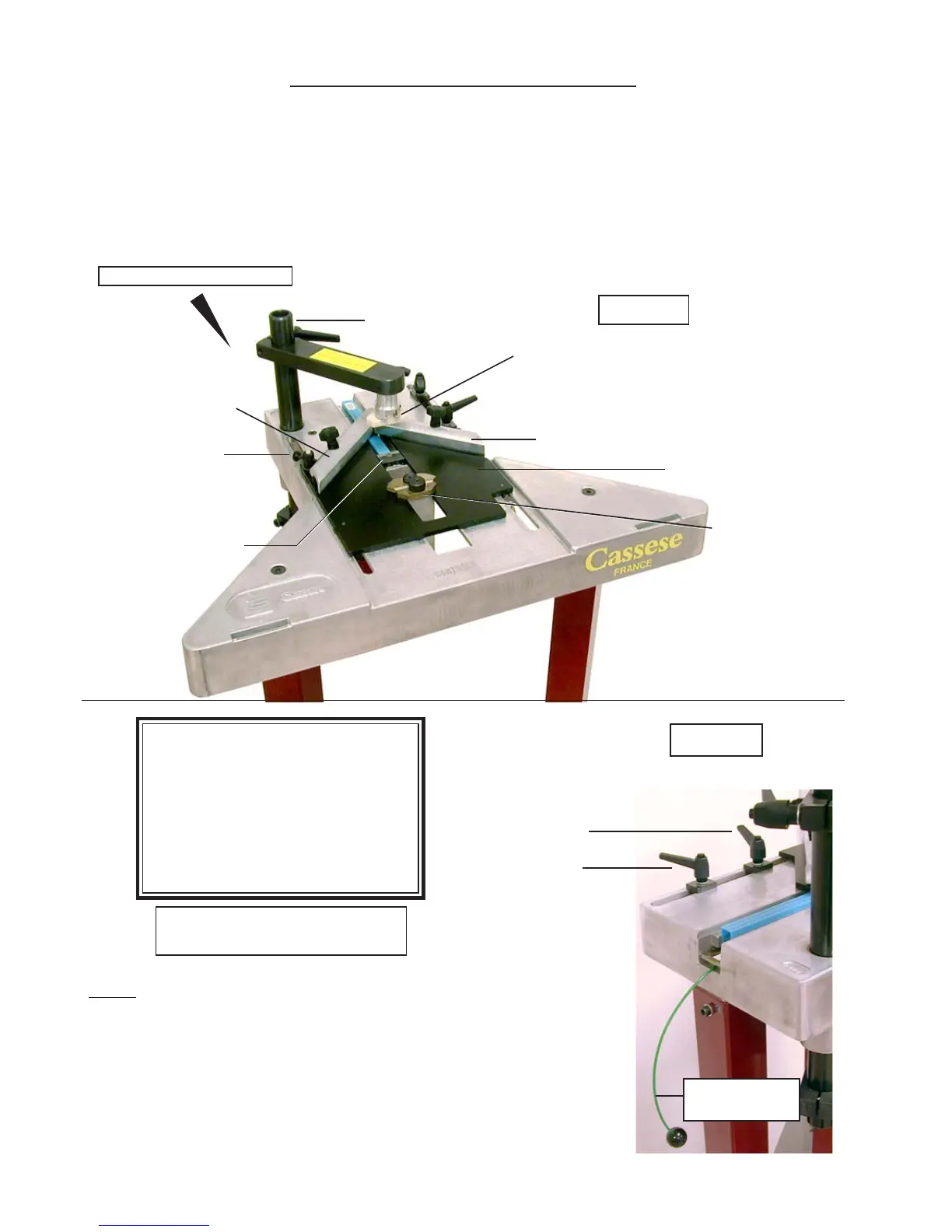
REFERENCE POSITION
Fig N°1
ANGLE
ADJUSTMENT
SCREW
TOP PRESSER
BRACKET
WEDGE
DISTRIBUTOR
SLIDING TABLE
TOP PRESSER
B1
LEFT BACKFENCE
HORIZONTAL
CLAMP /
REBATE CLAMP
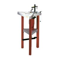
Fig N°2
STOP FOR
STAPLING
POINT
INNER SIDE OF
THE
FRAME
STOP FOR
STAPLING
POINT
OUTER SIDE
OF
THE FRAME
B2
RIGHT BACKFENCE
AS
IMPORTANT : For the best,
and most efficient function of
your CS 88-89 machine, we
advise you to carry out the ad-
justments exactly in the order
of this manual.
CS89 AIR CONNECTION
SEE PAGE 3
PUTTING INTO OPERATION
For safety during transportation, the moving parts of your CS 88 – 89 have been blocked : these
are the Top Presser Bracket (or Plunger) / Sliding Table / Horizontal (rebate) Clamp.
For the explanations given in this manual, the operator must be standing at the back of the
machine, keeping the machine slightly in his left. (See REFERENCE POSITION below). In this
position, the operator is always in the same distance to the corner, regardless of the size of the
frame.
Advice : to work frames of bigger sizes easily, you can put the CS 88-89
machines in front of your work bench (make sure that the work bench is not
higher than the machine). The CS 88-89 machines have been conceived in a
triangle form to fit any work bench : if you wish so, you can cut one of the
corners of your work bench, to locate the machine in this corner. This way,
while making big sized frames, you will not be using more than one of the
corners of your work bench.
WIRE FOR
WEDGE
PUSHING SPRING