1-2 FH100 Precision Variable-Speed Peristaltic Pump System Operating Manual Cole-Parmer
Section 1
Introduction
Controls, Indicators
and Connectors
Rear View
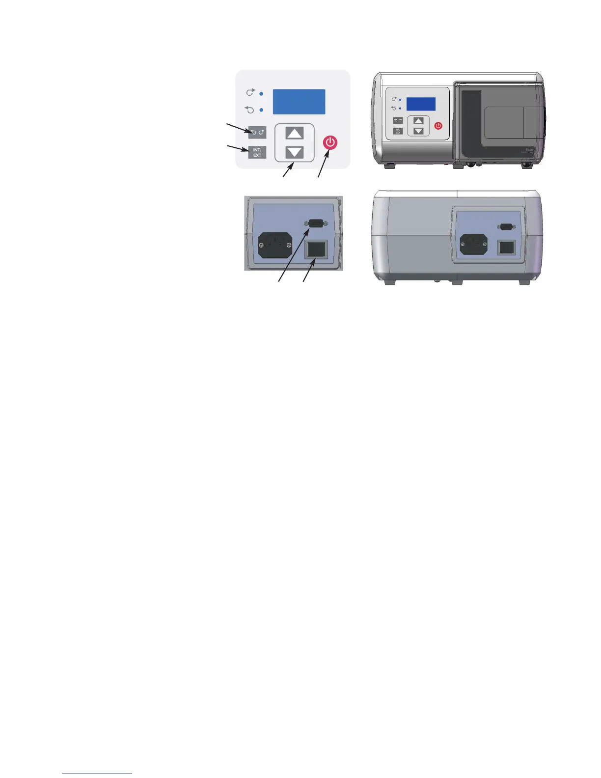
Figure 1-1. Controls, Indicators and Connectors
A
B
E
C
D
A. POWER (ON/OFF) SWITCH: Turns the unit ON or OFF.
B. SPEED KEYS: Sets the speed of the pump. The higher the number,
the faster the speed of the pump. When setting the displayed values,
units change first, then tens, etc. at an increasing rate.
C. FLOW DIRECTION KEY: Sets the direction of the rotation of the
pump Clockwise/Counterclockwise. An LED annunciator shows the
active direction. The motor is brought to a controlled stop before
reversing direction.
D. INTERNAL/EXTERNAL KEY: This key changes the mode of
operation for the drive. Internal (Local) operation throught the front
panel keypad is designated by “INT” while external (Remote)
operation is designated by “EXT”. In INT mode, START/STOP,
FLOW DIRECTION, and SPEED keys on the front panel
determine operating state. Pressing and releasing this key will toggle
between the two operating states.
E. START/STOP KEY: When depressed, this key toggles the motor on
and off when in INT mode. This key will not normally start the drive
if in EXT mode. If pressed while running in EXT mode (stop
desired), the button will always stop the drive and a toggle of the
EXT Start/Stop is required to restart the drive.
F. EXTERNAL/REMOTE CONNECTOR: Used to connect wiring for
remote control operation using a DB9 connector.
F
Front View