FH100 Precision Variable-Speed Peristaltic Pump System Operating Manual 3-3Cole-Parmer
Section 3
Operation
External Operation
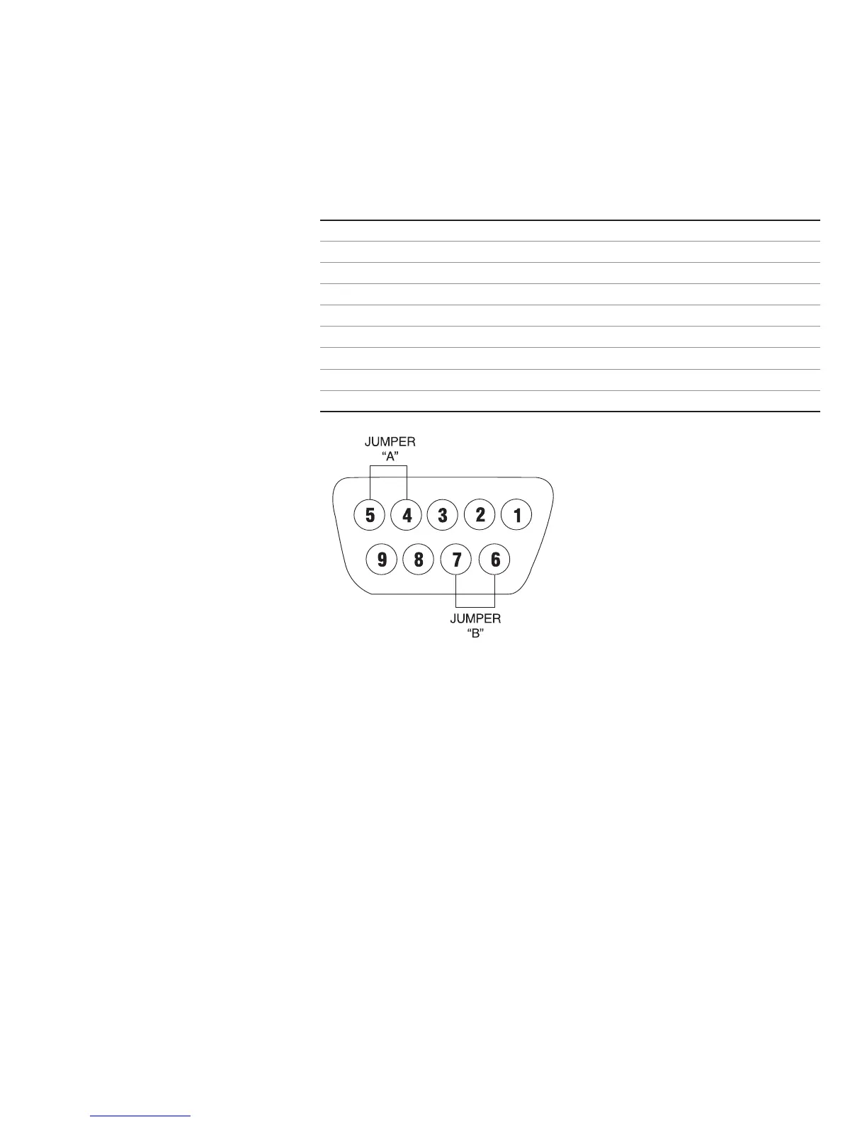
Models are equipped with inputs that can be controlled by external signals
connected at the rear panel 9-pin “D” shell connector. The External inputs
permit control of the pump by remote equipment or accessories. Figure 3-3
shows the signal locations of the connector.
Pin No. Description
1 Speed Control Voltage Input (0–10V) (+) input
2 Speed Control Current Input (4–20 mA) (+) input
3 Speed Control Input Reference Common
4 Local/Remote Speed Control
5 Local/Remote Speed Control Reference
6 Start/Stop and CW/CCW Reference
7 Start/Stop (+) Control
8 CW/CCW
9 Chassis (Earth) Ground
Figure 3-3. DB9 Pin Configuration with Wiring Scheme