EasyManuals Logo

Cattron CT24 Series User Manual

Default Icon
56 pages
To Next Page IconTo Next Page
To Previous Page IconTo Previous Page
Page #15 background imageLoading...
Page #15 background image
CT24 MCU
User Manual
15
9M02-7608-A001-EN
Version 2.0
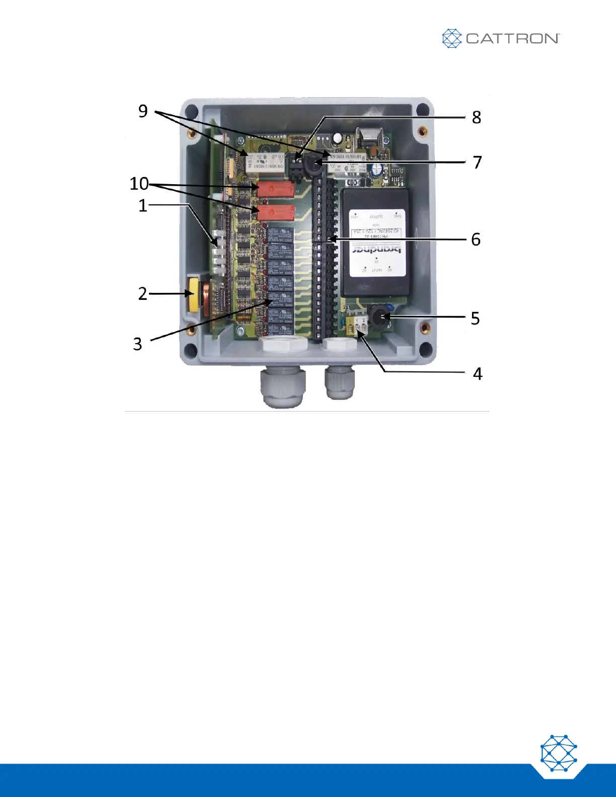
Figure 2: CT24-9 MCU
This MCU has two main contactor safety relays with one fuse and one pair of terminals, seven N/O relays and two
C/O relays. The following items are identified in Figure 2:
1. Status LEDs on micro board
2. TransKey inserted in slot inside enclosure
3. Seven N/O function relays
4. Terminal main input voltage
5. Fuse main input
6. Removable terminal strip for function relays
7. Fuse for main contactor safety relays
8. Terminal strip for main contactor safety relays
9. Two main contactor safety relays
10. Two C/O function relays

Table of Contents

Questions and Answers:

Question and Answer IconNeed help?

Do you have a question about the Cattron CT24 Series and is the answer not in the manual?

Cattron CT24 Series Specifications

General IconGeneral
BrandCattron
ModelCT24 Series
CategoryControl Unit
LanguageEnglish

Related product manuals