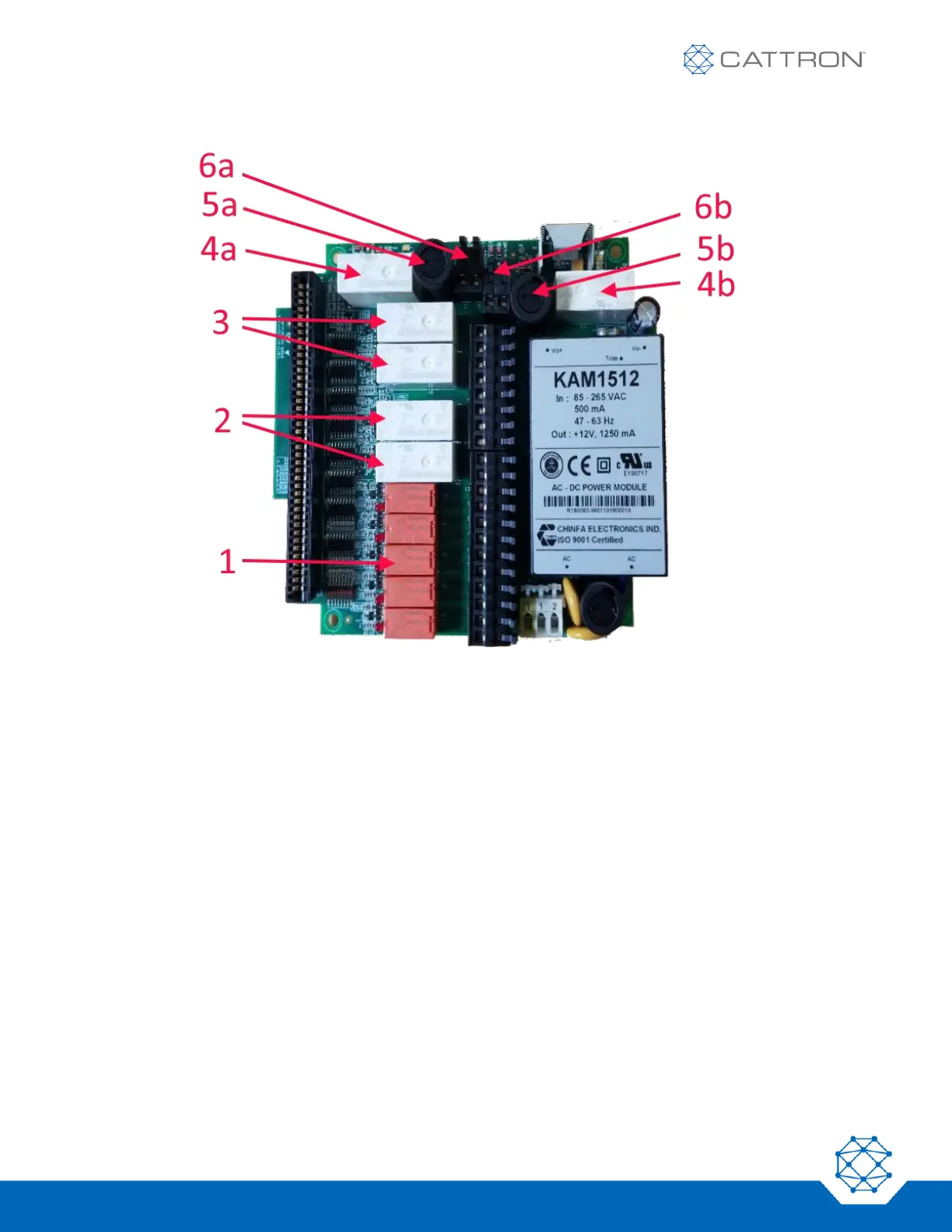
Figure 3: CT24-9-ASO MCU Printed Circuit Assembly
This MCU has an enhanced safety design with separated main contactor circuits and some upgraded function
relays resulting in two main contactor safety relays with two fuses and two pairs of terminals, five N/O relays, two
N/O safety relays and two C/O safety relays. The following items are identified in Figure 3:
1. Five N/O function relays
2. Two N/O function safety relays
3. Two C/O function safety relays
4. Main contactor safety relays
5. Fuses for main contactor safety relays
6. Terminals for main contactor safety relays
NB: If you are replacing a CT24-9 relay board with a CT24-9-ASO relay board, it will be necessary to link the two
safety main contactor relays in series with an additional link wire between the two terminal blocks 6a and 6b.
 Loading...