Location
- The PBX should be installed in a well ventilated area and at a place where there is no chance of liquid spilling over it or
moisture getting into it (Like in the Bathrooms etc).
- Direct sun light should not fall on the PBX.
- The PBX should be installed on the wall at a minimum of 2 ft height from the floor.
Note: The Company’s warrantee voids if the above points are not followed.
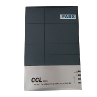
Front Panel Indications
Following are the descriptions of the 4 LED indicators of the front panel of the PBX:
LED Name Description
Line 1 Continuos ON indicates that Junction Line number 01 is used by the PBX
Line 2 Continuos ON indicates that Junction Line number 02 is used by the PBX
Line 3 Continuos ON indicates that Junction Line number 03 is used by the PBX
POWER Blinking means PBX is working on Mains AC or Battery.
/ Line 4 (In case of COX-416S, it also shows the status of the 4
th
Junction Line.
It gets continuous ON indicating Junction Line number 04 is used by the PBX)
Connections
The PBX has the following connectors on its side panel:
Connectors Description
Door - In default this connector is configured for Door Lock Operation.
- It can Optionally be used for Paging through an external PA Amplifier or to record communication of one
Extension/Junction at a time. This Option has to be mentioned while placing order with the company.
- For Door Lock operation, insert the 3 Pin stereo Plug here. The Shield point of the Plug is the common point.
Whenever, Door Lock operation command is given by any Extension, the “Shield Point” shorts with the
following points of the Jack:
Tip point of the Plug – in case of the 2
nd
Door Lock
Next to the Tip point of the Plug – in case of the 1st Door Lock
The above shorting acts as a simple switch.
Note: 2
nd
Door Lock operation is Optional.
Music For connecting External music for Music on Hold, insert the 3 Pin stereo Plug of the external Music source, here.
COM The Battery Lead provided with the system is to be connected here.
Connect 2 SMF rechargeable Batteries (12V 7AH) in series and connect to the Battery Lead. The RED wire is to
be connected to the +ve Terminal of the Battery and Black to the –ve Terminal. The 2 batteries are to be
connected in series with the help of a red colored shorting lead provided with the system.
The battery connections are on Pin number 5 & 6. Pin 5 = Gnd and Pin 6 = + 24V DC.
LINE 1 Terminate the 1st Junction Line here through a RJ Connector.
LINE 2 Terminate the 2nd Junction Line here through a RJ Connector.
LINE 3 Terminate the 3rd Junction Line here through a RJ Connector.
LINE NC Not Connected / Not to be used
LINE 4 In case of COX-416, terminate the 4th Junction Line here through a RJ Connector.
EXT 601 Terminate the 1st Extension wires over here through a RJ Connector.
EXT 602 Terminate the 2nd Extension wires over here through a RJ Connector.
EXT 603 Terminate the 3rd Extension wires over here through a RJ Connector.
EXT 604 Terminate the 4th Extension wires over here through a RJ Connector.
EXT 605 Terminate the 5th Extension wires over here through a RJ Connector.
EXT 606 Terminate the 6th Extension wires over here through a RJ Connector.
EXT 607 Terminate the 7th Extension wires over here through a RJ Connector.
EXT 608 Terminate the 8th Extension wires over here through a RJ Connector.
EXT 609 Terminate the 9th Extension wires over here through a RJ Connector.
EXT 610 Terminate the 10th Extension wires over here through a RJ Connector.
EXT 611 Terminate the 11th Extension wires over here through a RJ Connector.
EXT 612 Terminate the 12th Extension wires over here through a RJ Connector.
EXT 613 Terminate the 13th Extension wires over here through a RJ Connector.