Injectors replacement of
top burners
Every cooker is provided with a set of injec-
tors for the various types of gas.
Injectors not supplied can be obtained
from the After-Sales Service.
Select the injectors to be replaced accord-
ing to the table at page 39.
The nozzle diameters, expressed in hun-
dredths of a millimetre, are marked on the
body of each injector.
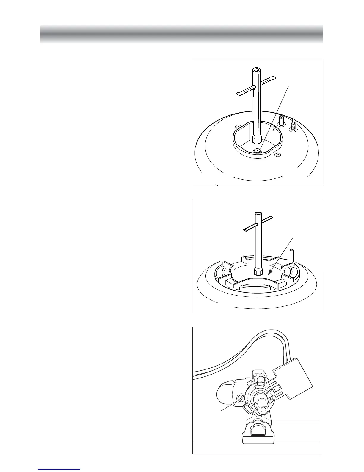
To replace the injectors proceed as follows:
– Remove the grids and extract the burner
bodies.
– Using a wrench, substitute the nozzle
injectors “J” (Figs. 44a - 44b) with those
most suitable for the kind of gas for
which it is to be used (see “Table for the
choice of the injectors”).
The burners are constructed in such a
way so as not to require the regula-
tion of the primary air.
Adjusting of the minimum
of the top burners
Considering that in the minimum position
the flame must have a length of about 4
mm and must remain lit even with a quick
turn from the maximum position to that of
minimum.
The flame adjustment is done in the follow-
ing way:
– Turn on the burner
– Turn the tap to the MINIMUM position
– Take off the knob
– With a thin screwdriver