3
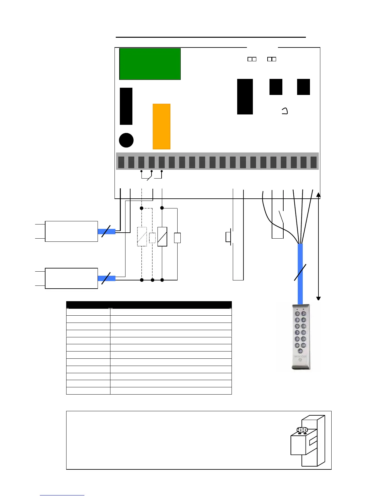
WIRING DIAGRAM PROFIL100EC 1 RELAY OUTPUT
V : Varistors
Terminal Description
V Input voltage 12/24 VAC or 12/48 VDC
V Input voltage 12/24 VAC or 12/48 VDC
R1 Contact repos du relais 1
C1 Commun du relais 1
T1 Contact travail du relais 1
P1 Request-to-exit input relay 1
M Common of input
PX Yellow wire request-to-enter Bell button
H Timer Contact
+ White wire keypad
- Brown wire keypad
E Green wire (illumination)
This device comes with a varistor.
The varistor must be connected on the strike terminal (electromagnet…) operated
by the device.
If this product operates more than one strike, each lock should have a varistor.
The varistor controls the overload produced by the strike coil – back emf.
It is recommended to use a separate power supply when using a Shear Lock
Magnet.
Green
Distance 10
meters
maximum
P1