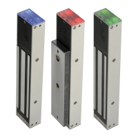
Electromagnetic locks surface mount series
INSTALLATION MANUEL
4
cdvi.com
cdvigroup.com
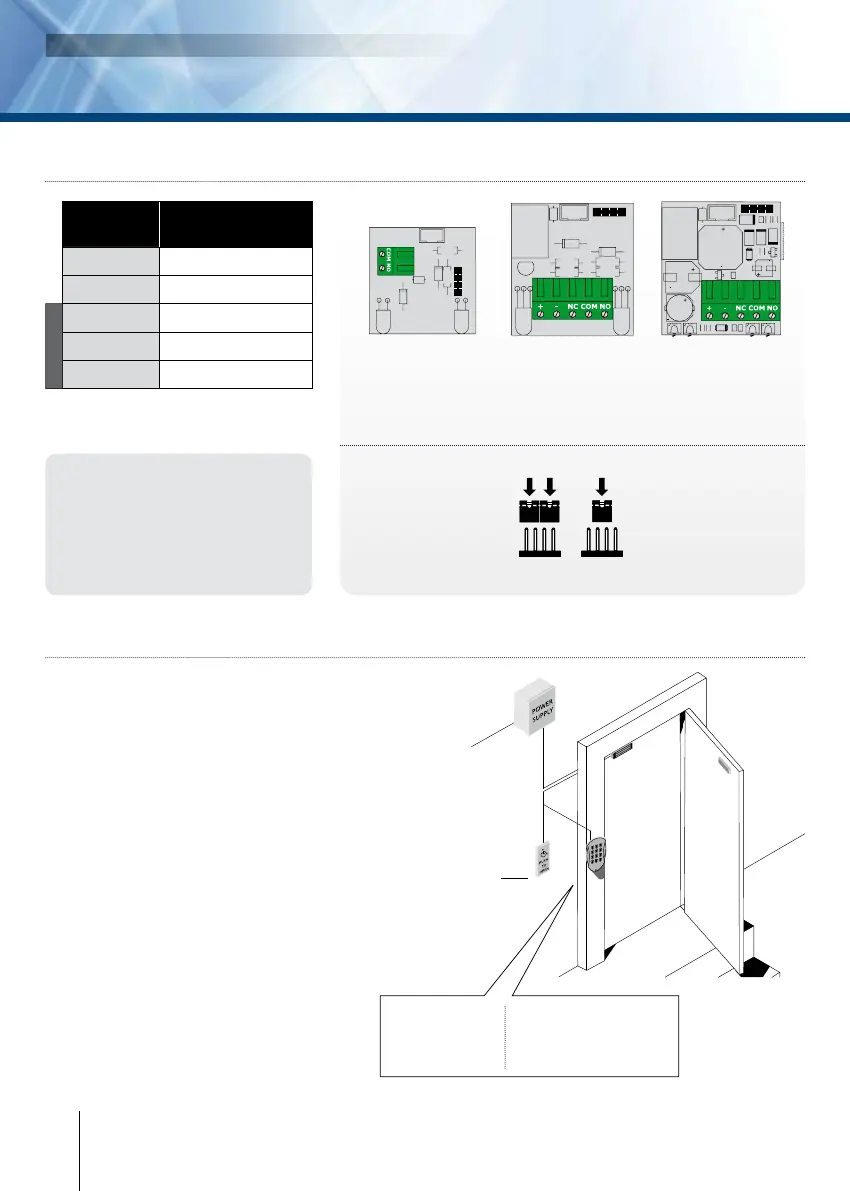
5] INSTALLATION INSTRUCTIONS:
- Identify the type of door (inward
or outward opening) and choose
an optional accessory if necessary.
- Drill a hole in the door jamb
to route the cable to the lock.
- Fix the mounting plate rmly
to the door frame.
- Position the armature
and accessory, if any, on the door
and check that it is tted but not
jammed. The electromagnetic lock
may be tted vertically or
horizontally on the door frame.
- Align the armature opposite the lock.
- Check that the lock is set to the
right voltage and apply the current.
When the door is closed the
armature should attach strongly
to the lock.
4] ELECTRICAL CONNECTIONS
Important note:
Check the jumper position before
connecting the lock to the 24 V DC
input current. A wrong position
could damage the lock. This type
of damage is not covered by the
warranty.
12V dc 24V dc
Current input
220/230V ac
Power supply
12/24V dc
Inside “Exit”
request push button
Outside “access
conrol” unit
Examples:
1. Proximity reader
2. Digicode
®
3. MIFARE
®
reader
Electromagnet
300, 400 and 500Kg
lock + Buzzer
Ref. CDVI and CDVI UK:
V3SRB - V4SRB - V5SRB
300, 400 and 500Kg
lock, version with relay.
Ref. CDVI:
V3SR - V4SR - V5SR
Ref. CDVI UK:
S300M - S400M - S500M
300, 400 and 500Kg
lock + blue lighting
Ref. CDVI:
V3S - V4S - V5S
Ref. CDVI UK:
S300 - S400 - S500
The NO/NC signal only switches when
the door is closed with the power to it on.
Voltage selection jumpers
Terminal
block
Correspondence
+ 12 or 24V dc
- -0 V
N.C
Normally closed
COM
COM
N.O
Normally open
Signal