7
ENGLISH
EN
Introduction 7
Description 7
Technical data 7
Usage limits (IEC 60974-1) 7
How to lift up the machine 8
Open the packaging 8
Installation 8
Connection to the electrical supply 8
Usage norms 8
MMA electrode welding 8
TIG welding 10
Maintenance 10
Possible problems and remedies 10
Procedure for welder assembly and disassembly 10
Electro topographical diagram
Colour key
Electro topographical diagram key
Meaning of graphic symbols on machine
Meaning of graphic symbols on rating plate
Spare parts list
Ordering spare parts
•
The generator also conforms to all European Union stan-
dards and directives in force.
Technical data
The general technical data of the system are summarized in
table 1.
Usage limits (IEC 60974-1)
The use of a welder is typically discontinuous, in that it is made
up of effective work periods (welding) and rest periods (for the
positioning of parts, the replacement of wire and underflushing
operations etc. This welder is dimensioned to supply a I
2
max
nominal current in complete safety for a period of work of 25%
of the total usage time. The regulations in force establish the
total usage time to be 10 minutes. The work cycle is conside-
red to be 25% of this period of time. If the permitted work cy-
cle time is exceeded, an overheat cut-off occurs to protect the
components around the welder from dangerous overhea ting.
Intervention of the overheat cut-off is indicated by the lighting
up of yellow thermostat LED (Pos. 2, Fig. A). After several min-
utes the overheat cut-off rearms automatically (and the yel-
low LED turns itself off) and the welder is ready for use again.
Introduction
Thank you for purchasing one of our products. Please read in-
structions on use in this manual as well as the safety rules
given in the attached booklet and follow them carefully to get
the best performance from the plant and be sure that the parts
have the longest service life possible. In the interest of custom-
ers, you are recommended to have maintenance and, where
necessary, repairs carried out by the workshops of our service
organisation, since they have suitable equipment and specially
trained personnel available. All our machinery and systems are
subject to continual development. We must therefore reserve
the right to modify their construction and properties.
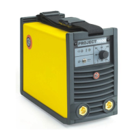
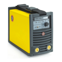
Description
PROJECT is an inverter that can be used for professional weld-
ing, with any type of electrode found on the market. It is ex-
tremely easy to use, guarantees excellent welding results and
can be used anywhere thanks to its compact size and reduced
weight (workshops, maintenance, construction sites, etc.). The
main characteristics of the PROJECT welding machine are:
• Reduced weight and size, easy-to-carry.
• Shoulder belt supplied standard for easy transport.
• It has an IP 23 S protection class so that it can be used un-
der the heaviest working conditions.
• Switch with two welding processes: electrode and TIG.
• Automatic “Hot Start” and “Hot Start”.
• Electrode Antisticking function.
• TIG welding with “Lift” striking.
Table 1
Model
PROJECT
1300 1600
Single-phase power supply
50/60 Hz
V 230
Mains supply: Z
max
(*) Ω 0,19
Power input @ I
2
Max kVA 6,3 6,7
Delayed fuse (I
2
@ 100%) A 16
Power factor / cosφ
0,62/0,99 0,60/0,99
Maximum efficiency degree η 0,82
Open circuit voltage V 60
Current range A 5÷130 5÷160
Duty cycle @ 100% (40°C) A 80 90
Duty cycle @ 60% (40°C) A 100 105
Duty cycle @ 25% (40°C) A 130 160
Usable electrodes mm 1,6÷3,25 1,6÷4
Standards
IEC 60974-1
IEC 60974-10
Insulation class IP 23 S
Protection class F
Dimensions
mm 315 - 230 - 135
Weight kg 6,1 6,3
(*) Mains supply Z
max
: maximum impedance value allowed for
the grid according to the EN/IEC 61000-3-11 standard.
WARNING: This equipment does not comply with EN/IEC
61000-3-12. If it is connected to a public low voltage system, it
is the responsibility of the installer or user of the equipment to
ensure, by consultation with the distribution network operator
if necessary, that the equipment may be connected.
16
16
17
18
19
20-21
22