Page: 14 of 15
Parameter Function Description Display Unit
01 00 Return water temperature 1°C
01 09 Flow water temperature 1°C
01 06 Outdoor air temperature 1°C
01 31 DHW sensor temperature 1°C
Number Parameter Default Minimum Maximum Unit
d0 01 00 Circulating warm return temperature - -20 100 1°C
d1 01 01 Compressor operating frequency - 0 200 1Hz
d2 01 02 Discharge temperature - -20 150 1°C
d3 01 03 Current consumption value - 0 9900 100W
d4 01 04 Fan control number of rotation - 0 1000 10rpm
d5 01 05 Defrost temperature - -20 100 1°C
d6 01 06 Outdoor air temperature - -20 100 1°C
d7 01 07 Water pump control number of rotation - 0 9900 100rpm
d8 01 08 Suction temperature - -20 100 1°C
d9 01 09
Circulating water outgoing temperature
- -20 100 1°C
System Operational Checks
Once the heat pump is set up, it is a very good idea to check that everything works as intended and that
the heat pump starts and stops when it should in response to the controls used, and there is a good ow rate
at the manifolds and radiators get hot.
Checking Sensor Values
Ensure these temperatures are recorded when the heat pump is running steadily.
Alternatively these can be viewed from the outdoor units terminal PCB.
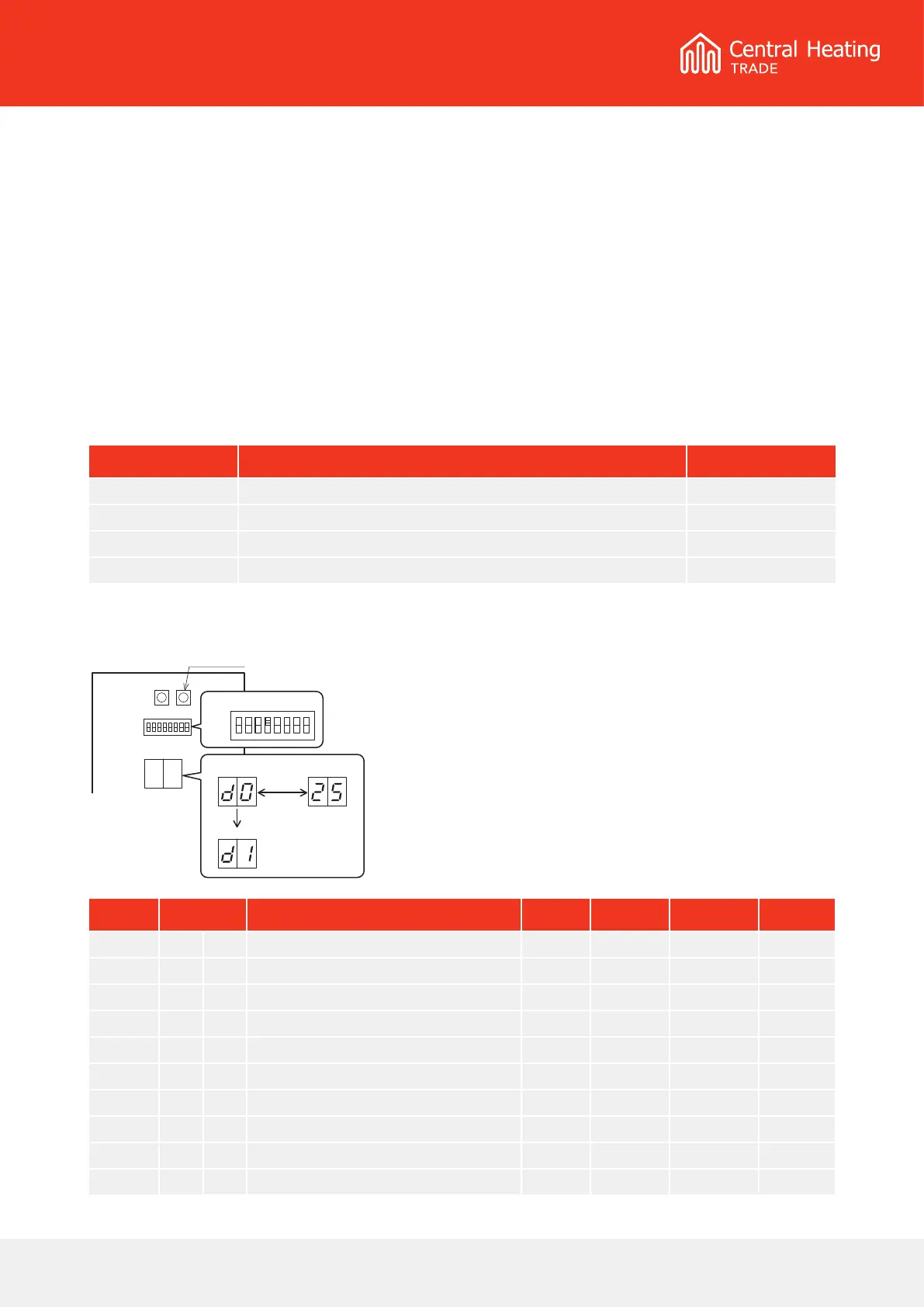
Display on PCB (Terminal) display
• Turn On the dip SW4 on the PCB (Terminal) to display
the monitor number and monitor data alternately.
• Push the Pump SW, of the PCB (Terminal) to switch
the display number alternately.
• To return to normal display, turn O the Dip SW4.
PCB(Terminal)
Pump SW.
ON
OFF
number
change number
Pump SW.
monitor data
alternately
Dip SW4 = ON