EasyManua.ls Logo

Central Machinery 58358 - User Manual

Central Machinery 58358
20 pages
Print Icon
To Next Page IconTo Next Page
Loading...
Visit our website at: http://www.harborfreight.com
Email our technical support at: productsupport@harborfreight.com
Owners Manual & Safety Instructions
Save This Manual Keep this manual for the safety warnings and precautions, assembly,
operating, inspection, maintenance and cleaning procedures. Write the product’s serial number in the
back of the manual (or month and year of purchase if product has no number). Keep this manual and the
receipt in a safe and dry place for future reference. 22g
When unpacking, make sure that the product is intact
and undamaged. If any parts are missing or broken,
please call 1-888-866-5797 as soon as possible.
Copyright
©
2021 by Harbor Freight Tools
®
. All rights reserved.
No portion of this manual or any artwork contained herein may be reproduced in
any shape or form without the express written consent of Harbor Freight Tools.
Diagrams within this manual may not be drawn proportionally. Due to continuing
improvements, actual product may differ slightly from the product described herein.
Tools required for assembly and service may not be included.
Read this material before using this product.
Failure to do so can result in serious injury.
SAVE THIS MANUAL.
Question and Answer IconNeed help?

Do you have a question about the Central Machinery 58358 and is the answer not in the manual?

Summary

Owners Manual & Safety Instructions

Save This Manual

Keep this manual for safety warnings, assembly, operation, and maintenance procedures.

General Warning

Critical safety alert to read the manual before using the product to prevent serious injury.

Warning Symbols and Definitions

Symbol Definitions

Explains safety alert symbols like Danger, Warning, Caution, and Notice.

Important Safety Information

General Tool Safety Warnings

Essential safety guidelines for operating power tools to prevent electric shock, fire, and injury.

Grounding Instructions

110-120 VAC Grounded Tools

Instructions for using tools with three-prong plugs and proper grounding connections.

Lathe Tool Safety Warnings

Specifications

Setup - Before Use

Assembly;Mounting

Steps for assembling and mounting the tool rest on the lathe.

Functions

Operating Instructions

Tool Set Up

Procedures for setting up the tool, including work area preparation and leveling.

Workpiece and Work Area Set Up

Guidelines for designating a clean, well-lit work area and preparing the lathe's placement.

General Operating Instructions

Basic steps for operating the lathe safely, including power connection and shutdown.

Adjusting Spindle Speed

Adjusting the Tailstock

Adjusting the Tool Rest

Install and Remove Spur Center

Install and Remove Live Center

Install and Remove Faceplate

Power Switch Safety Key

Operating Instructions (Spindle Turning)

Operating Instructions (Faceplate Turning)

Maintenance and Servicing

Cleaning, Maintenance, and Lubrication

Procedures for inspecting, cleaning, and lubricating the lathe for optimal performance.

Troubleshooting

Parts List and Diagram

Parts List

A comprehensive list of all parts included with the wood lathe.

Assembly Diagram

Limited 90 Day Warranty

Overview

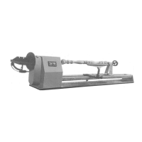
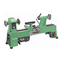
This document is an owner's manual and safety instructions for the Central Machinery 5-Speed Wood Pen Lathe, Item 58358. It provides comprehensive information on the device's function, technical specifications, usage, and maintenance.

Function Description:

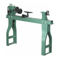
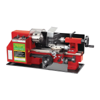
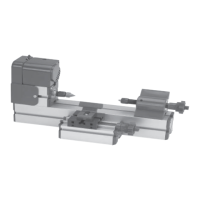
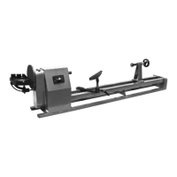
The Central Machinery 5-Speed Wood Pen Lathe is a power tool designed for turning wood, specifically for creating items like pens, bowls, and other small wooden objects. It operates by rotating a workpiece at high speed while a user shapes it with various cutting tools. The lathe features a headstock, tailstock, and tool rest, which are essential for securing and supporting the workpiece during the turning process. The headstock contains the spindle, which holds and rotates the workpiece, while the tailstock provides support to the opposite end of the workpiece. The tool rest allows the user to brace cutting tools for precise shaping. The lathe offers five different spindle speeds, allowing for versatility in working with various wood types and achieving different turning effects. It is equipped with a power switch that includes a safety key to prevent unauthorized use. The design emphasizes user safety through various warnings and instructions for proper setup, operation, and maintenance.

Important Technical Specifications:

  • Electrical Rating: 110VAC / 60Hz / 370W / 3.3A
  • Spindle Speeds: 760 / 1100 / 1600 / 2200 / 3200 RPM (5-speed)
  • Spindle Size: 1" x 8 TPI
  • Swing Over Bed: 10"
  • Swing Over Tool Rest: 7-1/4"
  • Tailstock Taper: MT2
  • Tailstock Quill Bore: 3/8"
  • Tailstock Quill Travel: 1-3/4"
  • Weight: 77 lbs
  • Distance Between Centers: 18" Max.

Usage Features:

The lathe is designed for ease of setup and operation, with clear instructions provided for various tasks:

  • Tool Rest Installation: The tool rest is installed by loosening a lock lever, inserting the tool rest into its base, and then retightening the lever.
  • Spindle Speed Adjustment: To adjust the spindle speed, the user must first turn off and unplug the tool. Then, they loosen the motor mount screw and lock lever, pull up the belt tension lever to release tension, and tighten the lock lever to hold the motor in a raised position. After opening the pulley cover and side plate, the drive belt can be moved to the desired grooves on the drive pulley and motor pulley according to the speed chart. Finally, the motor mount screw is retightened, and the covers are replaced. The belt tension is adjusted to allow 1/2" deflection.
  • Tailstock Adjustment: The tailstock can be moved to the desired position by loosening and then retightening the release lever. Instructions are provided for adjusting the clamping pressure if the tailstock does not release or lock properly.
  • Tool Rest Adjustment: The tool rest base can be slid along the bed by loosening and retightening the lock handle. The tool rest itself can be adjusted vertically or swiveled by loosening and retightening its lock lever.
  • Spur Center Installation/Removal: The tapered end of the headstock spur center is inserted into the headstock spindle with a quick pull to secure it. Removal involves inserting a knockout rod through the balance wheel and spindle and tapping it until the spur center comes out. The user is advised to hold the spur center to prevent damage.
  • Live Center Installation/Removal: The live center is installed by loosening the lock lever, rotating the tailstock handwheel to protrude the tail axis, inserting the live center, and then retightening the lock lever. Removal involves loosening the lock lever and rotating the handwheel counterclockwise until the tail axis bottoms out, forcing the live center out.
  • Faceplate Installation/Removal: The faceplate is threaded onto the headstock spindle and secured with a set screw. Removal involves loosening the set screw, holding the balance wheel, and turning the faceplate counterclockwise with a wrench. If a spur center is installed, it should be removed first.
  • Power Switch Safety Key: The lathe includes a yellow safety key for the power switch to prevent unauthorized use. The key must be inserted to turn the lathe on and removed to lock it in the "OFF" position.
  • Workpiece Setup: Detailed instructions are provided for setting up both spindle turning and faceplate turning operations. This includes marking the center of the workpiece, drilling pilot holes, driving the headstock spur center into the workpiece, positioning the tailstock and live center, and adjusting the tool rest for optimal clearance. For faceplate turning, the workpiece is attached to the faceplate using non-tapered wood screws or by gluing a backing block to the workpiece.
  • Sanding and Finishing: The manual recommends removing the tool rest and using a low speed when sanding or finishing to increase safety and working room.

Maintenance Features:

The manual outlines essential maintenance procedures to ensure the longevity and safe operation of the lathe:

  • Pre-Use Inspection: Before each use, a general inspection of the tool is required, checking for loose hardware, misalignment or binding of moving parts, cracked or broken parts, damaged electrical wiring, and any other conditions that might affect safe operation.
  • Post-Use Cleaning: After use, external surfaces of the tool should be wiped with a clean cloth.
  • Dust Removal: Periodically, the motor vents should be blown out with dry compressed air while wearing ANSI-approved safety goggles and NIOSH-approved breathing protection.
  • Lubrication: All external moving parts should be lubricated daily with ISO 68 or SAE 20W oil. The tailstock oiling point requires lubrication every five uses or weekly if used frequently.
  • Damaged Cord Replacement: A critical safety warning states that if the supply cord is damaged, it must be replaced only by a qualified service technician.
  • Troubleshooting Guide: A troubleshooting section helps users diagnose and resolve common issues such as poor cut quality, excessive vibration, and the lathe not turning on or off. It provides possible causes and likely solutions for each problem, emphasizing safety precautions and disconnecting power before service.
  • Parts List and Diagram: The manual includes a comprehensive parts list and an assembly diagram, serving as a reference tool for identifying components. It explicitly states that all repairs and part replacements should be undertaken by certified and licensed technicians, not the buyer, to ensure safety and proper function.

The document also includes general tool safety warnings, grounding instructions for 110-120 VAC grounded tools, and specific lathe tool safety warnings, all aimed at preventing electric shock, fire, and serious injury. Vibration safety guidelines are also provided to mitigate the risk of vibration-related injuries. The product comes with a Limited 90 Day Warranty covering defects in materials and workmanship.

Central Machinery 58358 Specifications

General IconGeneral
BrandCentral Machinery
Model58358
CategoryLathe
LanguageEnglish

Related product manuals