EasyManua.ls Logo

Central Machinery 59220 - User Manual

Central Machinery 59220
24 pages
Print Icon
To Next Page IconTo Next Page
Loading...
Visit our website at: http://www.harborfreight.com
Email our technical support at: productsupport@harborfreight.com
Owners Manual & Safety Instructions
Save This Manual Keep this manual for the safety warnings and precautions, assembly,
operating, inspection, maintenance and cleaning procedures. Write the product’s serial number in the
back of the manual (or month and year of purchase if product has no number). Keep this manual and the
receipt in a safe and dry place for future reference. 22h
When unpacking, make sure that the product is intact
and undamaged. If any parts are missing or broken,
please call 1-888-866-5797 as soon as possible.
Copyright
©
2022 by Harbor Freight Tools
®
. All rights reserved.
No portion of this manual or any artwork contained herein may be reproduced in
any shape or form without the express written consent of Harbor Freight Tools.
Diagrams within this manual may not be drawn proportionally. Due to continuing
improvements, actual product may differ slightly from the product described herein.
Tools required for assembly and service may not be included.
Read this material before using this product.
Failure to do so can result in serious injury.
SAVE THIS MANUAL.
Question and Answer IconNeed help?

Do you have a question about the Central Machinery 59220 and is the answer not in the manual?

Overview

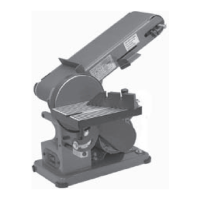
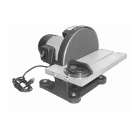
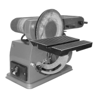
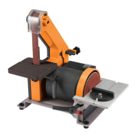
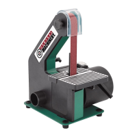
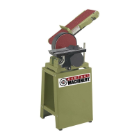
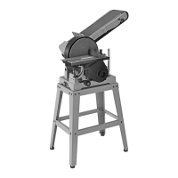
This document describes the Central Machinery 6" x 48" Belt and 9" Disc Sander, a versatile power tool designed for various sanding applications.

Function Description

The 6" x 48" Belt and 9" Disc Sander is a combination sanding machine that allows for both belt and disc sanding operations. It is designed to sand wood, plastic, and other materials, providing a smooth finish. The belt sander is suitable for sanding flat surfaces, edges, and contours, while the disc sander is ideal for shaping, beveling, and smoothing smaller workpieces. The machine is equipped with a work table that can be adjusted for both belt and disc sanding, allowing for precise angle adjustments. It also features a dust collection system to help maintain a clean work area.

Important Technical Specifications

  • Electrical Rating: 120VAC / 60Hz / 12A
  • Belt Size: 6" W x 48" L
  • Disc Size: 9"
  • Maximum Speed: 1800 RPM (Disc), 1400 FPM (Belt)
  • Motor: The motor drives both the sanding belt and disc.
  • Work Table: Adjustable for both belt and disc sanding.
  • Dust Ports: Equipped with dust ports for connecting to a dust collection system.
  • Safety Key: A removable safety key prevents unauthorized use.

Usage Features

The sander offers several features to enhance its usability and versatility:

  • Adjustable Work Table: The work table can be tilted and positioned for both belt and disc sanding, allowing for precise angle adjustments for bevels and chamfers. For the disc sander, the table can be set at a maximum of 1/16 inch from the sanding disc.
  • Adjustable Belt Frame: The sanding belt frame can be adjusted from a horizontal to a vertical position or any angle in-between, providing flexibility for different sanding tasks.
  • Tracking Lock Knob and Dial: These features allow for precise adjustment of the sanding belt's tracking, ensuring the belt stays centered on the rollers during operation.
  • Miter Gauge: Included for accurate angle sanding on the disc.
  • Dust Collection: The sander is equipped with two dust ports to connect to a dust collection system, which helps to minimize airborne dust and maintain a cleaner work environment.
  • Safety Switch with Safety Key: The power switch includes a removable safety key, which prevents the sander from being turned on accidentally or by unauthorized users. The switch must be in the "off" position before plugging in the tool.
  • Workpiece Support: The work table provides support for workpieces, ensuring stability and control during sanding.
  • Easy Belt and Disc Replacement: The manual provides instructions for replacing both the sanding belt and disc, making maintenance straightforward.
  • Drive Belt Tensioning: The drive belt tension can be adjusted to ensure optimal performance and prevent slippage.

Maintenance Features

Regular maintenance is crucial for the longevity and safe operation of the sander. Key maintenance features and procedures include:

  • Cleaning, Maintenance, and Lubrication:
    • Before Each Use: Inspect the general condition of the tool, checking for loose hardware, misalignment or binding of moving parts, cracked or broken parts, damaged electrical wiring, and any other condition that may affect its safe operation.
    • After Use: Turn off the tool, remove the safety key from the switch, and disconnect its power supply. Then, wipe external surfaces of the tool with a clean cloth.
    • Lubrication: Apply a light coat of paste wax to the work table to make feeding material easier.
    • Dust and Debris Removal: Periodically wear ANSI-approved safety goggles and NIOSH-approved breathing protection and blow dust and debris out of the motor vents using dry compressed air.
    • Bearings: The bearings on this sander are sealed and do not require lubrication.
  • Sanding Disc Replacement:
    • Remove the work table.
    • Remove the screws holding the disc guard in place.
    • Peel off the old sanding disc.
    • Wipe down the backing disc with denatured alcohol to remove any residue and ensure a secure bond.
    • Remove backing from the new sanding disc.
    • Align the perimeter of the new sanding disc over the backing disc and press firmly onto the backing disc.
    • Position the disc guard back in place and replace the screws.
  • Sanding Belt Replacement/Tensioning:
    • Remove the work table.
    • Remove the screws holding the disc guard.
    • Loosen the M8x10mm set screw on the backing disc and slide the disc off the drive shaft.
    • Loosen the four M8x20mm motor mount bolts that hold the motor.
    • Move the motor forward to relieve drive belt tension.
    • Check drive belt tension by squeezing both sides of the belt toward each other. When properly adjusted, the belt should deflect approximately from 1/8 to 1/4 inch. Make sure the belt is properly seated in the grooves of both pulleys.
    • When belt tensioning is complete, reinstall the backing disc and disc guard.
  • Adjusting Sanding Belt Tracking:
    • Make sure the belt tracking dials are evenly tightened on both sides and that the sanding belt is sufficiently tight.
    • Spin the belt down by hand to note any gross side to side movement. The belt should remain centered on the front and rear drums. If the belt starts moving to the side of either drum, it needs to be adjusted.
    • If the belt moves to the left, increase tension on the left side tracking dial. If the belt moves to the right, increase tension on the right side tracking dial.
    • Do fine-tune tracking, turn the sander on and immediately off again after adjustment to check alignment.
    • If necessary, continue to adjust the belt tracking dials until the belt rides in the center of the front and rear drums, then tighten the tracking lock knobs.
  • Changing Sanding Belt Frame Position:
    • Loosen the sanding belt frame lock nut and raise the sanding belt frame to the desired vertical position/angle.
    • After positioning, wrench tighten the lock nut securely to prevent the sanding belt frame from slipping.

This comprehensive description covers the key aspects of the Central Machinery 6" x 48" Belt and 9" Disc Sander, providing a clear understanding of its capabilities and requirements.

Central Machinery 59220 Specifications

General IconGeneral
BrandCentral Machinery
Model59220
CategorySander
LanguageEnglish

Related product manuals