EasyManuals Logo

Cervis TM70 Operation & Installation Manual

Default Icon
16 pages
To Next Page IconTo Next Page
To Previous Page IconTo Previous Page
Page #8 background imageLoading...
Page #8 background image
TM70Bi.v1.1.doc (10/03) 7
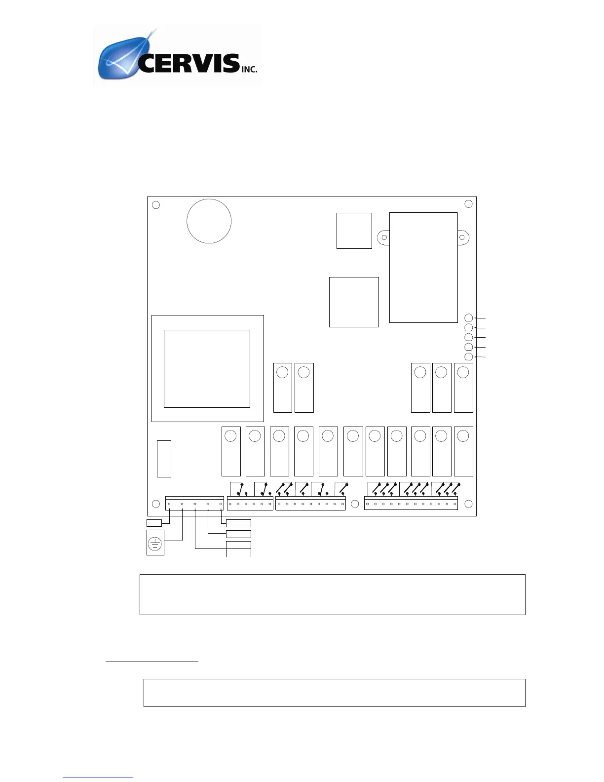
The STOP relays K15 and K16 are in series and must be connected to the main
contactor coil circuit.
The K2/START is activated once the start-up command is held down.
The K1/SEC relay is a security relay, which is activated when certain commands
predefined as “active” on configuration of the system, (i.e. commands which give rise to
movements), are activated.
Remember to connect the ground cable.
Only use fireproof cables for connections.
Select the appropriate voltage on the receiver, (230, 115 or 48 Vac)
4.3.- STARTING UP
Proceed with caution; the equipment may not be connected correctly
which may lead to unexpected movements upon start-up.
K16
K15
K12
K2
K14
K13
K11
K1
K10
K7
K8
K6
K5
K3
K4
SIGNAL
POWER
HA RDOK
ID
DA TA
FU
SE
1A
K14
K13
K12
STOP
K2
K1
K11
K10
K9
K8
K7
K6
K3
K4
K5
N23 0/ AC
+/AC
PE
N11 5/ AC
?/DC
N48 / AC

Other manuals for Cervis TM70

Questions and Answers:

Question and Answer IconNeed help?

Do you have a question about the Cervis TM70 and is the answer not in the manual?

Cervis TM70 Specifications

General IconGeneral
BrandCervis
ModelTM70
CategoryRemote Control
LanguageEnglish