TM70Bi.v1.1.doc (10/03) 8
Once the receiver has been connected, disconnect the power supply to the motors, (for
example, by removing the fuses) and power on the receiver. With this, the receiver will
enter into a ‘SCANNING’ mode and the following LED’s will be lit in the receiver;
POWER: ON, indicates that the power supply is correct.
HARDOK: ON, indicates the absence of faults on the boards.
SIGNAL: OFF in the case of the channels being signal free. Blinks ON when
there is a RF signal on the channels
DATA: OFF; when there is not another TM70 system active in the area.
Blinks ON in the opposite case..
ID: OFF
Next, turn transmitter ON to OPERATION mode, as follows:
Place a charged battery in the transmitter.
Turn the contact key clock wise for on.
Push and pull out the STOP button. LED flashes once orange and then green for 3
seconds. If the transmitter has an LCD, it displays the identification of the machine,
as well as the battery level.
Press the start button. The green LED should now light indicating that the
transmitter is transmitting.
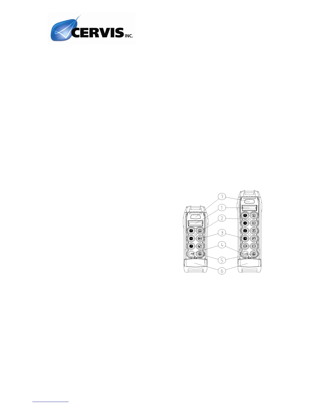
1.- Label for crane identification.
Optional: LCD Display
2.- LED.
3.- Command button
4.- Contact key
5.- Start button
6.- STOP button
7.- Option: Range Limiter
Upon receiving a signal from the transmitter, the following LED’s will light up on the
receiver:
POWER: ON, indicates that the power supply is correct.
HARDOK: ON, indicates that defects have not been detected on the board.
SIGNAL: ON, indicates that it is receiving a RF signal at the working frequency.
 Loading...