EasyManua.ls Logo

Cessna 1971 Super Skymaster - Page 52

Cessna 1971 Super Skymaster
63 pages
Print Icon
To Next Page IconTo Next Page
To Previous Page IconTo Previous Page
Loading...
I
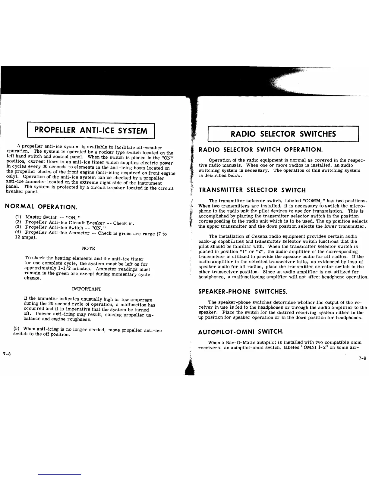
PROPELLER
ANTI-ICE
SYSTEM
A
propeller
anti-ice
system
is
available
to
facilitate
all-weather
operation.
The
system
is
operated
by
a
rocker
type
switch
located
on
the
left
hand
switch
and
control
panel. When the
switch
is
placed
in the "ON"
position,
current
flows to an
anti-ice
timer
which
supplies
electric
power
in
cycles
every
30
seconds
to
elements
in
the
anti-icing
boots
located
on
the
propeller
blades
of the
front
engine
(anti-icing
required
on
front
engine
only).
Operation
of the
anti-ice
system
can
be
checked
by a
propeller
anti-ice
ammeter
located
on the
extreme
right
side
of
the
instrument
panel.
The
system
is
protected
by a
circuit
breaker
located
in the
circuit
breaker
panel.
NORMAL
OPERATION.
(1)
Master
Switch
--
"ON. "
(2)
Propeller
Anti-Ice
Circuit
Breaker
--
Check
in.
(3)
Propeller
Anti-Ice
Switch
--
"ON. "
(4)
Propeller
Anti-Ice
Ammeter
--
Check
in
green
arc
range
(7
to
12
amps).
NOTE
To
check
the heating
elements
and the
anti-ice
timer
for
one
complete
cycle,
the
system
must
be
left
on
for
approximately
1-1/2
minutes.
Ammeter
readings
must
remain
in
the
green
arc
except
during
momentary
cycle
change.
IMPORTANT
If
the
ammeter
indicates
unusually high
or
low
amperage
during
the
30
second
cycle
of
operation,
a malfunction
has
occurred
and
it
is
imperative
that
the
system
be
turned
off. Uneven
anti-icing
may
result,
causing
propeller
un-
balance
and engine
roughness.
(5) When
anti-icing
is
no
longer
needed, move
propeller
anti-ice
switch
to
the off position.
r--RADIOSELECroR-swrrCHis-
J
RADIO
SELECTOR
SWITCH
OPERATION.
Operation
of
the
radio
equipment
is
normal
as
covered
in the
respec-
tive
radio
manuals.
When one
or
more
radios
is
installed,
an
audio
switching
system
is
necessary.
The
operation
of
this
switching
system
is
described
below.
TRANSMITTER
SELECTOR
SWITCH
" The
transmitter
selector
switch,
labeled
"COMM,
It
has
two
positions.
.f'
When two
transmitters
are
installed,
it
is
necessary
to
switch
the
micro-
i phone
to
the
radio
unit the
pilot
desires
to
use
for
transmission.
This
is
I.
accomplished
by placing the
transmitter
selector
switch
in the position
,
corresponding
to
the
radio
unit
which
is
to
be
used.
The up position
selects
,
the
upper
transmitter
and
the
down poSition
selects
the
lower
transmitter.
The
installation
of
Cessna
radio
equipment
provides
certain
audio
back-up
capabilities
and
transmitter
selector
switch
functions
that
the
pilot
should
be
familiar
with. When the
transmitter
selector
switch
is
placed
in
position
"1"
or
"2",
the audio
amplifier
of the
corresponding
transceiver
is
utilized
to
provide
the
speaker
audio
for
all
radios.
If
the
audio
amplifier
in
the
selected
transceiver
fails,
as
evidenced by
loss
of
speaker
audio
for
all
radiOS,
place
the
transmitter
selector
switch
in the
other
transceiver
position. Since an audio
amplifier
is
not
utilized
for
headphones, a malfunctioning
amplifier
will not affect headphone
operation.
SPEAKER-PHONE SWITCHES.
The
speaker
" phone
switches
determine
whether
.the output of the
re-
ceiver
in
use
is
fed
to
the
headphones
or
through the audio
amplifier
to
the
speaker.
Place
the switch
for
the
desired
receiving
system
either
in
the
up
position
for
speaker
operation
or
in
the down pOSition
for
headphones.
AUTOPILOT-OMNI
SWITCH.
When a
Nav-O-Matic
autopilot
is
installed
with
two
compatible
omni
receivers,
an
autopilot-omni
switch,
labeled
"OMNI
1-2"
on
some
air-
j
7-9
d
i
7-8
I