Citation SERVICE BULLETIN
SB560-34-114
H. Install the upper TCAS II antenna. (Refer to Cessna Engineering Drawing 9608042-5.)
NOTE: Before the installation of the upper and lower TCAS antennas the make sure of these
parameters:
• There are no L-band, specifically L-band transponder, antennas within 10 inches of the
specified installation location that could produce an interference or coupling ef fect.
• Therearenohighprofile antennas with in 30 inches of the specified installation
location that could produce a shadowing effect.
I. Install the lower TCAS II antenna. (Refer to Cessna Engineering Drawing 9608043-5.)
J. Install the transponder antennas. (Refer to Cessna Engineering Drawings 9608044-1 and
9608044-2.)
K. (Airplanes that do not have the TCAS I installed and are installing the TCAS II Computer at location
option B.) Install the ground blocks. (Refer to Cessna Engineering Drawing 9654613.)
L. (Airplanes installing TCAS Install the circuit breakers as shown. (Refer to Cessna Engineering
Drawing 9654207.)
NOTE: The right hand circuit breaker panel will already have TCAS circuit breaker locations labeled
and capped. Use these locations.
(1) Airplanes -0260 thru -0400, use the 9654207-3 installation.
(2) Airplanes -0401 thru -0538, use the 9654207-24 installation.
5. (Airplanes that are installing the TCAS II at location option A.) Install the 9656060-15 baggage closeout
installation. (Refer to Cessna Engineering Drawing 9656060.)
A. Airplanes that are installing the TCAS II at location option A for new installation of TCAS II will
also need the 4890407-10 Carpet.
NOTE: Order the corre
ct color carpet from Citation Parts Distribution, Telephone number
1-800-835-4000 (Domestic) or 316-517-7542 (International) or Telefax 316-517-7711. Refer
to the MATERIAL INFORMATION section of this service bulletin for the proper part number
of the carpet b
ased on your airplanes color scheme.
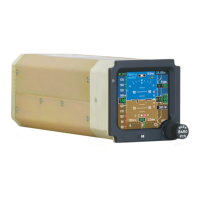
B. Change the Multifunction Display Controller located in either the instrument panel or pedestal.
(1) Remove the 7007062-939 Multifunction Display Controller. (Refer to the Maintenance Manual,
Chapter 34, Honeywell Primus 1000, Display and Flight Guidance System - Maintenance
Practices.)
(2) Send the removed 7007062-939 Multifunction Display Controller to Cessna Aircraft Company.
NOTE: Operators: The 7007062-939 Multifunction Display Controller may be upgraded.
Contact Cessna Citation Repairs to schedule modification at 1.866.349.8436
(US/Canada) or 1.316.517.8079 (International) or telefax 316.206.4068 or email to:
citationrepair@cessna.textron.com. This will require advance notification. Cessna
Citation Repairs will schedule the units and arrange for their return. Allow ten to
fourteen days for modification after receipt of parts from Citation Parts Distribution.
This service bulletin may not be signed off as completed unless the units are scheduled
through Cessna Citation Repairs.
(3) Install the 7007062-941 Multifunction Display Controller. (Refer to the Maintenance Manual,
Chapter 34, Honeywell Primus 1000, Display and Flight Guidance System - Maintenance
Practices.)
C. (Airplanes with the 7017000-80151 and 7017000-81151 IC-600 Display Guidance Computers)
Change the display guidance computers.
(1) Remove the 7017000-80151 and 7017000-81151 Display Guidance Computers. (Refer to the
Maintenance Manual, Chapter 34, Honeywell Primus 1000, Display and Flight Guidance
System - Maintenance Practices.)
Aug 13/2004 560-34-114
Revision 2 - Jan 2/2007 Page 11