Maneuvers
-
Normal
Category,
4-1
Manifold
Pressure
Gage,
1-6,
4-3
Ignition/Starter Switch, 1-6,
2-4
Map
Compartment,
1-6
Inspection
Diagram,
Exterior, iv
Map
Light, Control
Wheel,
2-3
Inspection
Service-Periods,
5-5
Marker Beacon
Indicator
Lights
Instrument
Markings, Engine,
4-2
and
Switch,
1-6
OPERATING
CHECK LIST
Instrument
Panel,
1-6
Master
Cylinders,
Brake,
5-9
Interior Care,
5-4
Master Switch, 1-6,
2-3,
2-4
Internal
Cabin
Dimensions,
4-10
Maximum
Glide,
6-8
Maximum
Performance
Climb,
1-4
One
of the
first steps in
obtaining
the
utmost
performance
service,
Maximum Performance
Take-Off,
and flying
enjoyment from
your Cessna is to familiarize yourself
with
your
1-3
airplane's
equipment,
systems, and
controls.
This can
best
be
done
by
L
Maximum
Rate-of-Climb
Data,
6-3
reviewing
this equipment while
sitting
in the
airplane.
Those items
whose
Microphone,
1-6
function and
operation are not obvious are covered in Section II.
.
.
Mixture
Control
Knob,
1-6,
2-2
Landing,
inside front
cover,
2-11
after,
1-5
Moment
Envelope,
Center of
Section
I
lists,
in Pilot's Check List
form, the steps necessary
to
balked,
1-5,
2-11
Gravity,
4-7
operate
your
airplane
efficiently
and
safely. It is not a
check list in its
before
1-4
Mooring
Your Airplane,
5-1
true form as it is
considerably longer,
but it does cover briefly àll of the
distance
table,
6-7
points
that you should know for
a
typical
flight.
normal,
1-5
Let-Down,
1-4
The
flight and
operational
characteristics of
your airplane are normal
Leveler,
Wing,
7-14
in
all
respects.
There are no "unconventional"
characteristics
or
opera-
emergency
procedures,
7-15
tions that need to
be mastered.
All
controls
respond
in
the
normal
way
operating
check list,
7-14
within
the
entire
range of
õperation. All airspeeds
mentioned in Sections
operating notes,
7-15
Non-Congealing
Oil Cooler,
7-1
I, H and HI are indicated
airspeeds. Corresponding
calibrated airspeeds
Limitations, Airspeed,
4-2
Normal
Category
Maneuvers,
4-1
may
be
obtained
from the
Airspeed Correction Table
in Section VI.
Limitations,
Engine
Operation,
4-2
Normal Chmb,
1-3
Line Drain
Plug, Fuel,
5-9
Normal Landing,
1-5
. .
Normal
Take-Off,
1-3
oaa
in
A
rlan
eentfro
8cover
BEFORE
ENTERING
THE
AIRPLANE.
Loading
Graph,
4-6
Loading Problem, Sample,
4-5
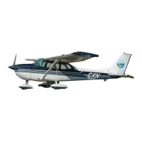
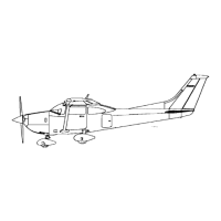
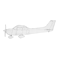
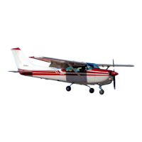
(1)
Make an exterior inspection in accordance
with
figure
1-1.
Long Range Fuel
Tanks,
7-1
Lubrication and
Servicing
Procedures,
5-7
Oil
System,
BEFORE
STARTING THE
ENGINE.
capacity,
inside
covers
dilution
switch,
1-6
(1) Seats
and
Seat
Belts
--
Adjust and
lock.
dilution system,
7-3
(2) Brakes
--
Test and set.
M
dilution
table,
7-3
(3)
Radios
and Electrical
Equipment
--
"OFF."
oil,
5-7, 5-8,
5-9, inside back
(4)
Fuel
Selector Valve
--
"BOTH ON.
"
Magnetic
Compass,
1-6
cover
(5) Wing Flaps
--
Check
all
positions.
Magnetos,
2-4
oil cooler,
non-congealing,
7-1
(6)
Cowl
Flaps
--
"OPEN.
"
(Move
lever
out
of locking
detent to
Main Wheel
Bearings,
5-10
oil
dipstick,
5-8
reposition.)
Index-4
1-1
 Loading...