5.5 Control PCB
5.5.1 Design and operating mode of the control PCB with LED v.1.0
The dimensions of control PCB is developed for using in the 19“plug-in device. Via guiding rails the con-
trol PCB gets through the module. On control PCB mounted diodes and Pushbuttons for inspection and
service are implemented in the front plate.
The connection plugs are located at the rear side of control PCB. Power supply plug, the connection to
analyzer and the plug for connection to the DCS. The control PCB is supplied by 24 V DC and protected by
a fuse. For a failure-free operation the voltage is stabilized onboard.
1
3
2
4
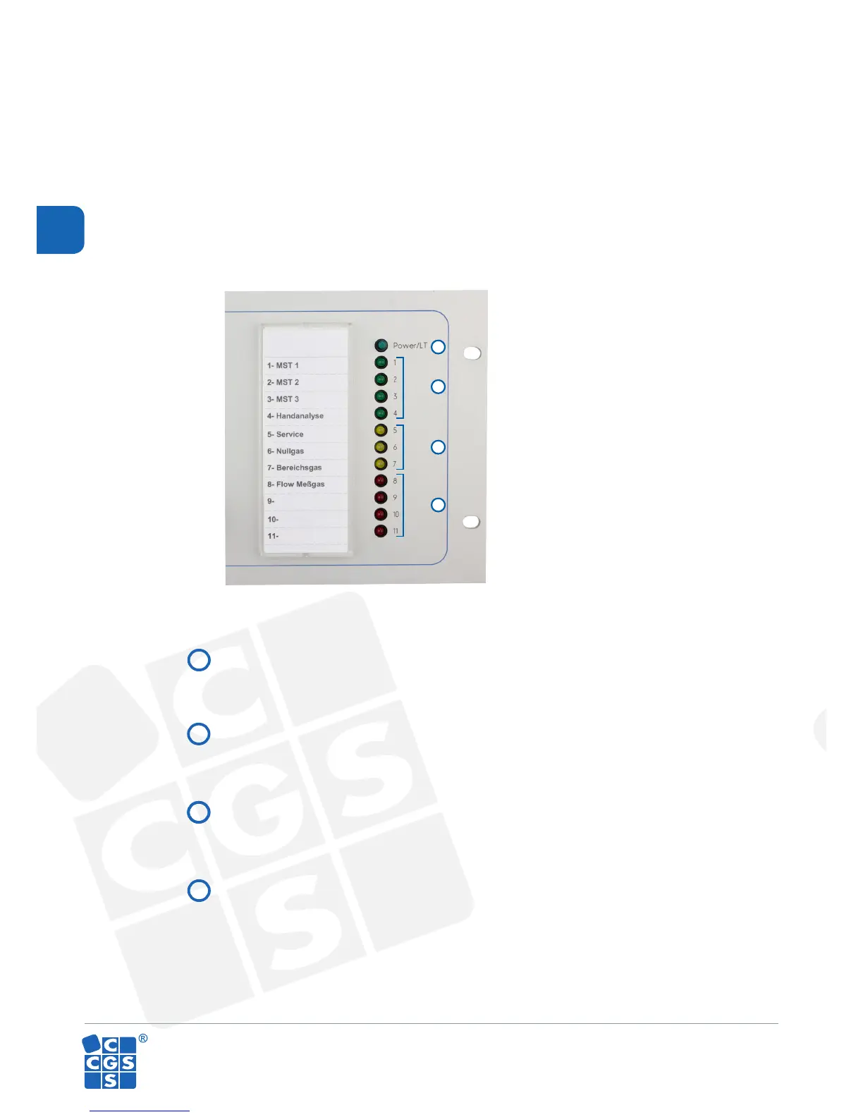
Pushbuttons
Green LEDs to display sample gases
Yellow LEDs to display service, zero and span gas
Red LEDs for FLOW- Sample gas/ or. costomized display variants
Used to test the lights on the front panel