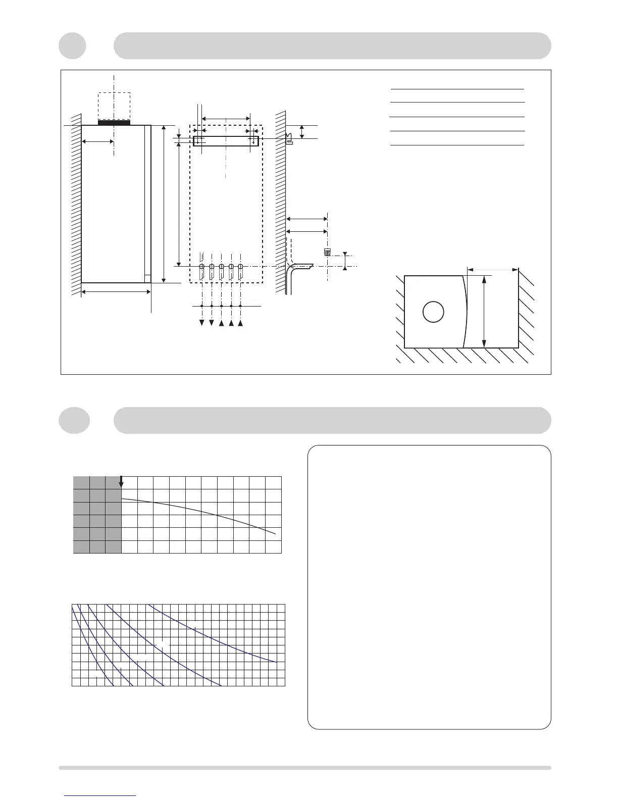
All dimensions in mm
With packaging :
24 kW : 32 kg
30 kW : 33 kg
.
10
Hydraulic Data
Fig. 9
Fig. 10
The boiler is fitted with an automatic by-pass as standard.
The graph (fig. 9) shows the development of the pressure
available in relation to flow on exit from the boiler. (Designed
temperature rise = 20
o
C).
To ensure correct operation, the minimum flow of the
appliance must be 300 l/h. (Thermostatic taps closed).
Capacity of the installation.
The water heater is fitted with a pressurised expansion
vessel.
Maximum. volume of expansion vessel: 6 litres.
Pressure: 1 bar.
The volume of the expansion vessel in a pressurised
appliance varies according to:
- the average operating temperature in °C
- the static height, which is the difference in metres between
the highest point of the appliance and the expansion vessel
axis).
The minimum cold filling pressure of the appliance is 1 bar
(recommended pressure between 1.2 and 1.7 bar).
The pressure of the expansion vessel should always be
greater than the static height (in metres) divided by 10.
390
minimum space required 450mm
I Safety valve C/H
J
Heating flow
K
D.H.W. flow
L
Gas supply
M
Cold water inlet
N
Heating return
C litre
Pump head available at the outlet of the boiler
System capacity chart
Pump head available
Minimum flow rate (with all heating thermostatic valves closed)
Central heating initial pressure when cold (in bar)
 Loading...