9
8
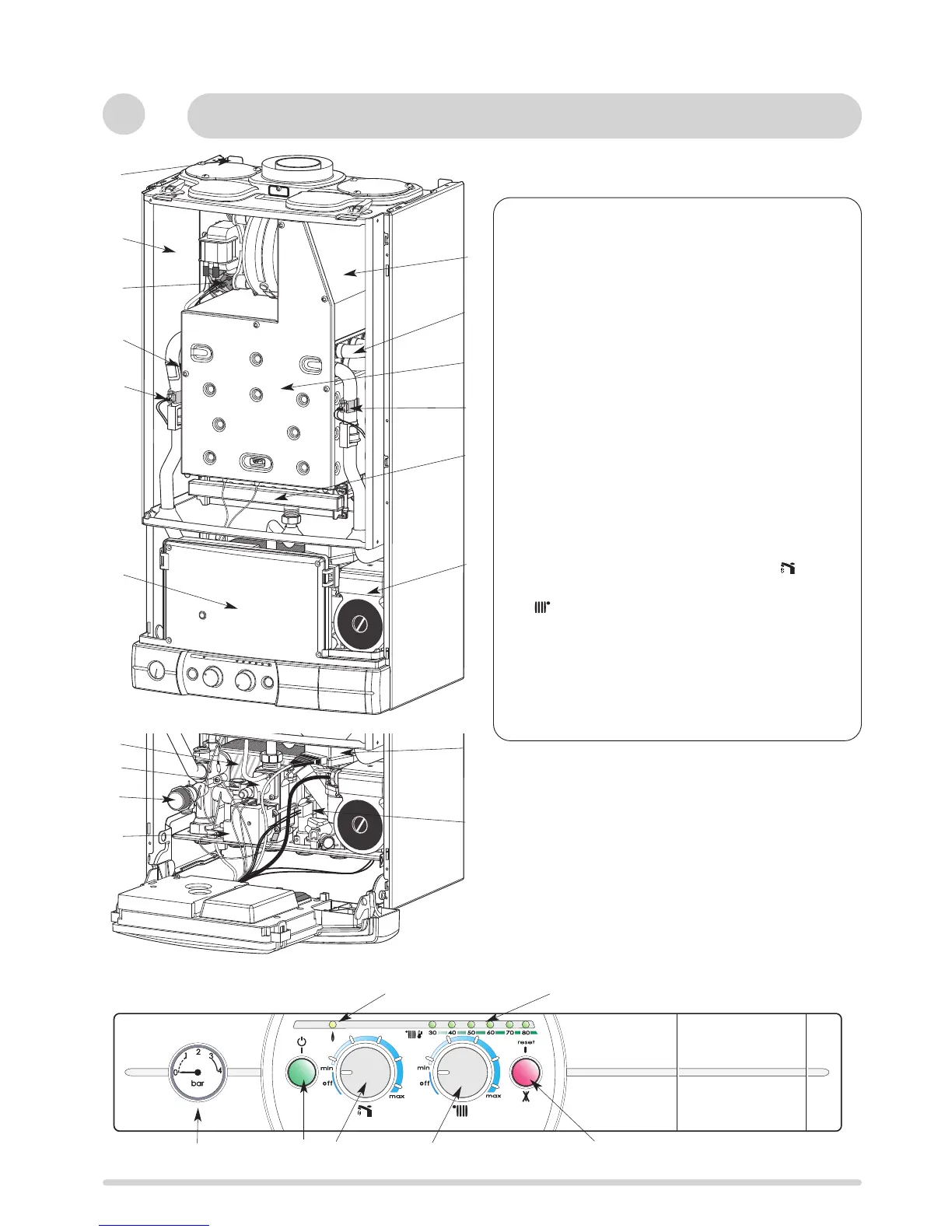
Description
INSTALLER’S INSTRUCTIONS
Fig. 5
1
2
14
4
5
6
12
3
10
15
17
16
18
Fig. 6
7
8
9
11
1.- Steel chassis complete with expansion vessel
2.- Sealed chamber
3.- Flue hood with fan
4.- Main heat exchanger
5.- Combustion chamber
6.- Multi-gas burner assembly comprising ignition and
ionisation electrodes
7.- Gas valve assembly
8.- Pump with automatic air separator and automatic vent
9.- Overheat safety cut-out
10 - Return thermistor
11.- Flow thermistor
12.- Electrical box
13.- Hot water flow sensor
14.- Air pressure switch
15.- Ignitor
16.- Central heating pressure relief valve
17.- Three way valve
18.- Secondary heat exchanger
19. - Pressure gauge
20. - On/off push button and power on indicator light
21.- DHW temperature setting and start button
22.- Central heating temperature setting and start button
23.- Heating temperature indicator and fault diagnostic
indicator
24.- Orange indicator - Burner ON
25.- Reset push button and red indicator lock-out light
13
20
21
23
25
22
24
19
Fig.7
c
 Loading...