5
USER’S INSTRUCTIONS
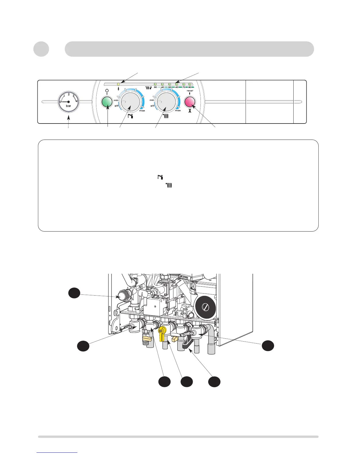
Control panel
(Fig. 1)
19. - Pressure gauge
20. - On/off push button and power on indicator light
21.- DHW water temperature setting and start button
22.- Central heating temperature setting and start button
23.- Heating temperature indicator and diagnostic indicator
24.- Orange indicator - Burner ON
25.- Reset push button and red indicator lockout light
Connecting bracket Taps shown in Open position
(Fig. 2)
31 : Central heating flow isolating valve
32 : Domestic hot water outlet
33 : Gas service tap
34 : Cold water service tap
35 : Central heating return isolating valve
16 : Central heating pressure relief valve
1
Control Panel
Fig. 2
31
32 33
34
35
16
20
21
23
25
22
24
19
c
Fig. 1
 Loading...