Chapter 2
14
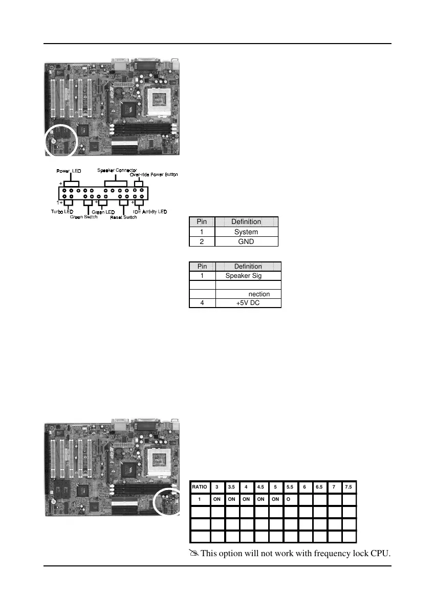
C. Green Switch/Green LED Connector
Some ATX cases provide a Green switch which
is used to put the system in Suspend mode. In
Suspend mode, the power supply to the system
is reduced to a trickle, the CPU clock is stopped,
and the CPU core is in it's minimum power state.
The system is woken up whenever the keyboard
or mouse is touched. The system resumes in
different ways as defined by Power Management
Setup screen in BIOS.
D. System Reset Switch Connector
This connector should be connected to the reset
switch on the front panel of the system case.
E. Speaker Connector
F. IDE Activity LED Connector
The IDE activity LED lights up whenever the
system reads/writes to the IDE devices.
G. Turbo LED Connector
This mainboard does not have a Turbo/De-turbo
speed modes. So the turbo LED will always light.
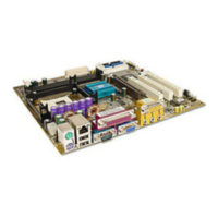
Optional CPU Clock Ratio Setting (SW1)
This feature allows you to set a CPU at a higher
clock ratio than it's specification allows. it may or
may not run at that ratio, depending on the quality
of your CPU and the extent to which the ratio has
been overset.
Pin Definition
1 System
2 GND
Pin Definition
1 Speaker Signal
2 No Connection
3 No Connection
4 +5V DC
This option will not work with frequency lock CPU.
!
RATIO 3 3.5 4 4.5 5 5.5 6 6.5 7 7.5
1 ON ON ON ON ON ON OFF OFF OFF OFF
2 ON OFF ON OFF ON OFF ON OFF ON OFF
3 ON ON OFF OFF OFF OFF ON ON ON ON
4 OFF OFF ON ON OFF OFF ON ON OFF OFF