EasyManua.ls Logo

Challenge CHAMPION 305 TC - User Manual

Challenge CHAMPION 305 TC
110 pages
Print Icon
To Next Page IconTo Next Page
Loading...
F.254-J
May 2014
CHAMPION 305 TC
Instruction and Parts Manual
Serial Numbers 1301701 & Up
Sold and Serviced by
The Challenge Machinery Company
6125 Norton Center Drive
Norton Shores, MI 49441-6081 USA
ChallengeMachinery.com
The Challenge Machinery Company provides owner's manuals on its
products solely as a courtesy to its customers. See the information below
before using this manual.
These manuals are for reference only. These manuals include products which are noncurrent,
unsupported or no longer produced by The Challenge Machinery Company, and are provided solely as
an accommodation to our customers. By providing these manuals, The Challenge Machinery Company
makes no representation or warranty as to the products, their current condition, or their suitability or
fitness for use in any particular application, which are the sole and independent responsibility of the
product owner and user.
Older products may not comply with current safety procedures, guidelines or regulations, and it
is the product owner's and user's responsibility to evaluate the suitability and fitness of the
products in their current use and application. The Challenge Machinery Company makes no
representation, warranty or recommendation regarding any modifications which may be
required on non-current or unsupported products. The Challenge Machinery Company assumes
no liability for any modification or alteration to any Challenge product, and any such
modification or alteration to any Challenge product is not authorized by The Challenge
Machinery Company. The availability of these manuals is solely for the purpose of providing reference
information for the products.
This manual may not be complete in all aspects of product maintenance and repair. All products
should be used only by qualified and properly trained personnel, following proper safety
procedures. All products should be regularly inspected and maintained, and their condition, application
and use should be periodically evaluated by qualified personnel. Only qualified and properly trained
technicians should perform maintenance, repair and replacement procedures. Attempting these
procedures without proper training may cause machine damage or operator injury!
Products may be unsupported by The Challenge Machinery Company due to age or the unavailability of
parts from their original manufacturer. No parts or product support will be available to repair or maintain
unsupported products. Older products may not be UL listed (if the product does not have a UL label it is
not a listed product), and may not comply with applicable installation or other regulations or
requirements if relocated to a new facility. Many municipalities require a product to be UL listed before
an electrician will connect power to them. Often the cost of updating an older product to comply with
current safety regulations is greater than the value of the product.

Table of Contents

Question and Answer IconNeed help?

Do you have a question about the Challenge CHAMPION 305 TC and is the answer not in the manual?

Summary

1.0 Introduction

Safety Alerts and Instructions

Safety alerts and personal safety instructions for operating the machine.

Read Manual Before Operation

Crucial instruction to read and understand the manual before operating the cutter.

Parts and Service Information

Guidance on obtaining parts and service from authorized dealers.

Record Machine Serial Number

Instruction to record the machine's serial number for reference.

Warranty Information

Information about warranty conditions and registration requirements.

2.0 Safety

Safety Precautions

Essential safety guidelines and precautions for operating the machine safely.

Power Lockout Procedure

Procedure for safely disconnecting power for maintenance or adjustments.

Warning Label Definitions

Explanation of various warning labels and symbols found on the machine.

3.0 Packing List

4.0 Specifications

5.0 Footprint

6.0 Installation & Setup

Inspecting Shipment

Procedure for checking the shipment for damage or missing items.

Uncrating

Instructions for safely removing the machine from its shipping container.

Lifting;Moving Instructions

Guidelines for safely lifting and moving the heavy machine.

Cleaning During Installation

Procedures for cleaning the machine during installation.

Assembly Procedures

Steps for assembling extension tables and shields.

Hydraulic Power Unit Removal

Procedure for removing the hydraulic power unit if needed for passage.

Hydraulic Check

How to check and maintain the hydraulic fluid level.

Power Hook-Up

Instructions for connecting the machine to the power supply.

7.0 Operation

False Clamp Plate Usage

How to install and use the false clamp plate for pressure-sensitive jobs.

8.0 Knife Installation;Changing

Knife Removal

Step-by-step instructions for safely removing the knife.

Knife Installation

Step-by-step instructions for safely installing a new knife.

Knife Care Tips

Advice and tips for maintaining knife performance and longevity.

9.0 Cleaning

Table Cleaning

Procedure for cleaning and maintaining the machine table.

Console Cleaning

Instructions for cleaning the control console.

Machine Frame Cleaning

Guidelines for cleaning the main machine frame.

10.0 Lubrication

11.0 Hydraulic System

Recommended Hydraulic Oil

Type of hydraulic oil recommended for the machine.

Changing the Hydraulic Oil

Procedure for draining and refilling the hydraulic oil.

Hydraulic Valve Adjustments

How to adjust hydraulic valves for optimal system performance.

12.0 Adjustments

Electric Eye Alignment

Procedure to align the electric eye safety system for proper function.

Backgauge Gib Adjustment

How to adjust the backgauge gibs for smooth and accurate movement.

Squaring the Backgauge

Method to test and adjust the backgauge for squareness.

Backgauge Position Accuracy Adjustment

Procedure to recalibrate the backgauge readout for accurate positioning.

Knife Latch Adjustment

How to adjust the knife latch to prevent accidental knife exposure.

Line Light Adjustment (Incandescent Type)

Adjusting the incandescent line light for visibility.

Line Light Adjustment (LED Type)

Adjusting the LED line light for visibility.

Proximity Switches Adjustment

Adjusting proximity switches for various machine functions.

Clamp Return Speed Adjustment

Adjusting the speed at which the clamp returns.

Pre-Clamp Pressure Adjustment

Adjusting low-pressure pneumatics for clamp pre-clamping.

Pre-Clamp Speed Adjustment

Adjusting the down speed of the clamp during pre-clamping.

Clamp Cylinder Adjustment (Clamp Height)

Adjusting the clamp cylinder for correct height.

Clamp Parallel Rod Adjustment

Adjusting the clamp parallel rod for alignment with the table.

Lead Screw Adjustment Nuts

Adjusting nuts on the lead screw to take up play.

Knife Bar Gibs Adjustment

Adjusting the knife bar gibs for smooth operation and accurate cuts.

13.0 Repair and Replacement

Fuses Replacement

Information on replacing fuses, including fire hazard warnings.

Knife Cylinder Replacement

Step-by-step procedure for replacing the knife cylinder.

14.0 Troubleshooting

Machine Wont Start Issues

Common issues and solutions when the machine fails to start.

Cut Buttons Cause Shutdown

Troubleshooting steps when cut buttons cause the machine to shut off.

Cut Buttons Activated, No Cut

Diagnosing issues when cut buttons are pressed but no cut occurs.

Erratic Operation and Power Loss

Identifying causes for erratic operation or power loss.

Clamp Wont Operate Issues

Solutions for when the clamp fails to operate correctly.

Clamp Wont Hold Pressure

Troubleshooting issues with the clamp not holding pressure.

Clamp Wont Bottom

Diagnosing why the clamp does not reach the bottom position.

Clamp Not Parallel to Table

Addressing misalignment of the clamp with the table.

Concave Cutting (Ends Wide, Center Narrow)

Causes and solutions for concave cutting patterns.

Concave Cutting (Top;Bottom Variation)

Diagnosing variations in cutting quality between top and bottom of stock.

Inconsistent Knife Stopping (Up Position)

Troubleshooting inconsistent knife stopping in the up position.

Knife Hesitation

Identifying reasons for knife hesitation during operation.

Knife Wont Return

Solutions for when the knife fails to return to the up position.

Clamp Wont Return

Troubleshooting issues with the clamp not returning properly.

Knife Drifts Down

Diagnosing why the knife drifts down from its position.

Knife Stops in Stock

Identifying causes for the knife stopping within the stock.

Noisy;Sluggish Hydraulic System

Troubleshooting causes for a noisy or sluggish hydraulic system.

Inaccurate Cutting Issues

Diagnosing and correcting issues leading to inaccurate cuts.

Erratic Backgauge Movement

Troubleshooting erratic backgauge movement.

Stock Drawing Issues

Identifying causes for stock being drawn or distorted during cutting.

Slow Knife Movement

Diagnosing why the knife movement is slow.

15.0 Schematics & Parts Lists

15.1 Main Assembly - Frame;Tank

Schematic and parts list for the machine's frame and hydraulic tank assembly.

15.2 Main Assembly - Hydraulics

Schematic and parts list for the machine's hydraulic system components.

15.3 Main Assembly - Clamp

Schematic and parts list for the clamp mechanism.

15.4 Main Assembly - Final Wiring

Wiring diagram and parts list for the machine's electrical connections.

15.5 Main Assembly - Electrical Components, Lower Front

Schematic and parts for front electrical components.

15.6 Main Assembly - Electrical Components, Upper

Schematic and parts for upper electrical components.

15.7 Main Assembly - Air Table

Schematic and parts for the air table assembly.

15.8 Main Assembly - Table Mounting

Schematic and parts for mounting the table to the machine.

15.9 Main Assembly - TC Backgauge

Schematic and parts for the TC backgauge system.

15.10 Main Assembly - Knife

Schematic and parts for the knife assembly.

15.11 Main Assembly - Covers and Labels

Schematic and parts for machine covers and labels.

15.12 Main Assembly - Table Extensions

Schematic and parts for optional table extensions.

15.13 Power Panel Assembly

Diagram and parts list for the main power panel.

15.14 Basic Machine Schematic

Overall schematic diagram of the machine's electrical system.

15.15 Interconnection Diagram

Diagram showing electrical interconnections between components.

15.16 Hydraulic Manifold Kit

Components and diagram for the hydraulic manifold kit.

15.16.1 Knife Down Sequence Valve Assembly

Diagram and parts for the knife down sequence valve.

15.16.2 Hydraulic Manifold Assembly

Diagram and parts for the hydraulic manifold assembly.

15.17 Hydraulic Schematic

Schematic illustrating the hydraulic system flow and components.

15.18 TC Control Console Assembly

Diagram and parts for the TC control console.

15.19 Electric Eye Assembly

Diagram and parts for the electric eye safety system.

15.20 Cut Button Assembly - Standard

Diagram and parts for the standard cut button assembly.

15.21 Cut Button Assembly - ErgoTouch

Diagram and parts for the ErgoTouch cut button assembly.

15.22 Knife Latch Assembly

Diagram and parts for the knife latch mechanism.

15.23 Line Light Assembly

Diagram and parts for the line light assembly.

15.24 Compressor Assembly

Diagram and parts for the compressor assembly.

15.25 Air Table Blower Assembly

Diagram and parts for the air table blower assembly.

15.26 Encoder Cable Assembly

Diagram and parts for the encoder cable assembly.

15.27 Power Panel Connection Procedure Label

Label detailing power panel connection procedures and warnings.

15.28 Warning Label

General warning labels for safety precautions.

15.29 Paper Deflector Kit (Option)

Parts list for the optional paper deflector kit.

15.29.1 Deflector & Shaft Assembly (Part of Paper Deflector Kit)

Diagram and parts for the deflector and shaft assembly.

16.0 Safety System Tests

Test #1: Electric Eye System Check

Procedure to test the electric eye's object detection capability.

Test #2: Cut Cycle Safety Stop

Procedure to test the safety stop during a cut cycle.
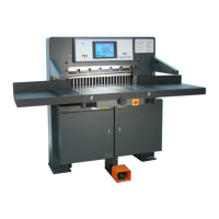
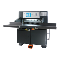
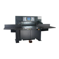
Challenge CHAMPION 305 TC Specifications

General IconGeneral
Max Cutting Width305 mm
Max Cutting Height50 mm
Narrow Cut5 mm
Cutting Length30.5"
Cutting Capacity50 mm

Related product manuals