This document is an installation, operation, and maintenance manual for the Challenger Lifts Models 15000 and 18000, which are two-post, surface-mounted vehicle lifts.
Function Description
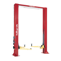
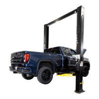
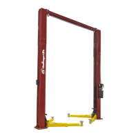
The Challenger Lifts Models 15000 and 18000 are hydraulic two-post vehicle lifts designed for automotive service. They are used to raise vehicles, providing access to the undercarriage for maintenance and repair. The lifts are surface-mounted, meaning they are installed directly on the concrete floor of a service bay. The design includes two columns, a power unit, hydraulic lines, synchronizer cables, and adjustable lifting arms with screw pads. An overhead shutoff bar is incorporated for safety, stopping the lift if a vehicle makes contact with it at its highest point. The lifts feature a locking pawl system for safety, ensuring the vehicle remains elevated at specific lock positions.
Important Technical Specifications
The manual provides detailed specifications for both models:
-
Model 15000:
- Maximum Capacity: 15,000 lbs (3750 lbs per arm)
- Column Height (A): 174" [14'-6"] or 198" [16'-6"] (with extension)
- Floor to Overhead Switch (B): 167" [13'-11"] or 191" [15'-11"] (with extension)
- Rise Height (Screw Pads Highest Position) (C): 85 1/2"
- Screw Pad Height (D): 6 5/8" to 16 1/2"
- Inside of Columns (E): 119 7/8"
- Overall Width (F): 154 3/4"
- Drive Thru Clearance: 104 1/4"
- Ceiling Height Required: 176"
- Lifting Time: Approximately 60 seconds
- Motor: 2HP, 1PH, 60Hz, 208/230 VAC (Optional: 2HP, 3PH, 50/60Hz, for 208/230 or 460 VAC)
-
Model 18000:
- Maximum Capacity: 18,000 lbs (4500 lbs per arm)
- Column Height (A): 174" [14'-6"] or 198" [16'-6"] (with extension)
- Floor to Overhead Switch (B): 167" [13'-11"] or 191" [15'-11"] (with extension)
- Rise Height (Screw Pads Highest Position) (C): 85 1/2"
- Screw Pad Height (D): 6 5/8" to 16 1/2"
- Inside of Columns (E): 119 7/8"
- Overall Width (F): 154 3/4"
- Drive Thru Clearance: 104 1/4"
- Ceiling Height Required: 176"
- Lifting Time: Approximately 60 seconds
- Motor: 3HP, 1PH, 60Hz, 208/230 VAC (Optional: 2HP, 3PH, 50/60Hz, for 208/230 or 460 VAC)
Both models require a minimum concrete depth of 4 inches with steel reinforcement, 3500 psi concrete cured for 28 days, and the floor must be level within 3/8 inch over the installation area. No anchors should be installed within 8 inches of any crack, edge, or expansion joint. Electrical requirements specify a dedicated circuit with a double pole 25 amp circuit breaker or time delay fuse for single-phase units. The lift is evaluated for indoor use only with an ambient temperature range of 5 - 40°C (41-104°F).
Usage Features
The lifts are designed for ease of use and safety in a service environment.
- Vehicle Positioning: Operators must center the vehicle between the columns, ensuring the center of gravity is midway between the adapters. The manual explicitly warns against exceeding the per-arm capacity (3750 lbs for Model 15000, 4500 lbs for Model 18000) and lifting with only two arms.
- Lifting Arms and Adapters: The adjustable arms and screw pads are positioned to contact the vehicle simultaneously at the manufacturer's recommended lifting points. Height extenders should be used when necessary to ensure good contact.
- Safety Locks: The lift incorporates safety latches on both columns. After raising the vehicle, it should be lowered onto these locks before personnel enter the area beneath. The latches must engage simultaneously; if not, the lift should be raised slightly and re-engaged.
- Overhead Limit Switch: A safety feature that stops the lift if the vehicle makes contact with the overhead shutoff bar, preventing damage.
- Lowering Procedure: To lower the vehicle, the area must be clear of personnel and tools. The lift is first raised slightly to free the latches, then the lock release button is pressed and held while the lowering valve handle is depressed. The vehicle is lowered until the carriages stop against the base plate, and then the extension arms are retracted and parked.
- Arm Restraints: The arm restraint gears should engage when the lift is raised and disengage when fully lowered.
- Hydraulic System: The system uses clean 10wt anti-foam anti-rust hydraulic oil or Dexron III ATF; detergents are explicitly prohibited.
Maintenance Features
The manual emphasizes the importance of proper maintenance for safe operation and provides a comprehensive checklist.
- Daily Maintenance:
- Keep lift components clean.
- Check for loose or broken parts.
- Inspect the hydraulic system for fluid leaks.
- Check adapters for damage or excessive wear and replace with genuine Challenger Lifts parts as needed.
- Verify lock release activation: the idler column lock should rest firmly against the back of the column when engaged and against the spring mount tab when disengaged.
- Weekly Maintenance:
- Check synchronizer cables and sheaves for wear and replace with genuine Challenger Lifts parts as required.
- Adjust synchronizer cable tension as per installation instructions.
- Monthly Maintenance:
- Torque concrete anchor bolts to 80 ft-lbs.
- Visually inspect the concrete floor for cracks and/or spalls within 12" of the base plate.
- Check the overhead shutoff switch by operating the shutoff bar while raising the lift; the power unit motor should stop.
- Lubricate carriage slide tracks with heavy viscous grease at all four corners of both columns.
- Hydraulic System Checks: If the lift stops short of full rise or chatters, operators should check the fluid level and bleed both cylinders.
- Decal Replacement: All safety, warning, or caution labels must be replaced if missing or damaged.
- Owner/Employer Responsibilities: The manual outlines the owner/employer's duties, including ensuring operators are qualified and trained, establishing periodic inspection and maintenance procedures, maintaining records, and displaying operating instructions and safety manuals in a conspicuous location.
- Troubleshooting: If any problems are encountered, users are instructed to contact their local service representative.