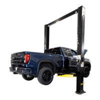
The provided document is an installation, operation, and maintenance manual for the CL Challenger Lifts CL10V3 and CL10V3-QC (Quick Cycle) models. This device is a Versymmetric® Two Post Surface Mounted Lift designed for vehicle lifting in automotive service bays.
Function Description
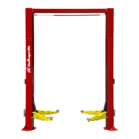
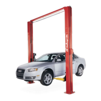
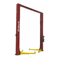
The Challenger CL10V3 series lift is designed to raise vehicles for maintenance and repair. It features a two-post, surface-mounted design, meaning the columns are installed directly onto the concrete floor. The "Versymmetric®" designation suggests a versatile arm design that can accommodate a wide range of vehicles by allowing symmetric or asymmetric lifting configurations. The lift operates hydraulically, using a power unit to extend cylinders that raise carriages, which in turn lift the vehicle via adjustable arms and screw pads. Safety features include locking pawls to secure the lift at various heights and an overhead limit switch to prevent over-raising.
Important Technical Specifications
The CL10V3 series lifts have a 10,000 lbs. (4536 kg) lifting capacity, with each arm capable of supporting 2500 lbs. (1134 kg).
Dimensions and Clearance:
- Column Height (A):
- CL10: 11'-2" or 11'-8" (3.40 m or 3.56 m)
- CL10-2: 13'-2" or 13'-8" (4.01 m or 4.17 m)
- CL10-3: 14'-2" or 14'-8" (4.32 m or 4.47 m)
- Floor to Overhead Switch (B):
- CL10: 10'-8 1/2" or 11'-2 1/2" (3.26 m or 3.42 m)
- CL10-2: 12'-8 1/2" or 13'-2 1/2" (3.87 m or 4.02 m)
- CL10-3: 13'-8 1/2" or 14'-2 1/2" (4.18 m or 4.33 m)
- Rise Height (Screw Pads Highest Position) (C): 74 1/8" (1.88 m)
- Cylinder Height (Full Stroke) (D): 11'-11" (3.63 m)
- Adjustable Overall Width (E): 11'-11" or 11'-6 1/2" (3.63 m or 3.52 m)
- Screw Pad Height (F): 3 7/8" to 6 1/8" (9.84 cm to 15.56 cm)
- Inside of Columns (G): 110" or 114 1/2" (2.79 m or 2.91 m)
- Arm Reach Front/Rear (Min.-Max.): Front (20"-42" / 50.8 cm - 106.7 cm), Rear (37-5/8"-60" / 95.6 cm - 152.4 cm)
- Drive Thru Clearance: 100" or 104 1/2" (2.54 m or 2.65 m)
- Ceiling Height Required:
- CL10: 11'-7" or 11'-11" (3.53 m or 3.63 m)
- CL10-2: 13'-3" or 13'-9" (4.04 m or 4.19 m)
- CL10-3: 14'-3" or 14'-9" (4.34 m or 4.50 m)
Performance:
- Lifting Time:
- Standard: 38 Sec. (approximate)
- Quick Cycle (CL10V3-QC): 24 Sec. (approximate)
- Hydraulic Pressure at Cap.: 2750 psi (189.6 bar)
Electrical Requirements:
- Motor:
- Standard: 2Hp, 1Ph, 60Hz, 208/230V
- Optional: 2Hp, 3Ph, 50/60Hz, 208/230/460V; 3Hp, 1Ph, 60Hz, 208/230V
- Requires a dedicated circuit with circuit breaker or time delay fuse.
Installation Requirements:
- Concrete Floor: Minimum 4 inches (10.16 cm) depth, steel reinforcement, 3500 psi (24.13 MPa) cured for 28 days. Floor must be level within 3/8 inch (0.95 cm) over the installation area. No anchors within 8 inches (20.32 cm) of cracks, edges, or expansion joints.
- Anchoring: 3/4-inch (1.91 cm) carbide bit for drilling, anchor bolts must be installed at least 8" (20.32 cm) from any crack, edge, or expansion joint. Torque anchor bolts to 150 ft-lbs (203.37 Nm).
- Operating Environment: Indoor use only, ambient temperature range of 5 - 40°C (41-104°F).
Usage Features
- Versymmetric® Design: Allows for flexible vehicle positioning and lifting, accommodating a wide range of vehicle types.
- Adjustable Overall Width: The lift's overall width can be adjusted to 11'-11" or 11'-6 1/2", providing flexibility for different bay sizes.
- Quick Cycle Option (CL10V3-QC): Offers a faster lifting time of approximately 24 seconds, improving efficiency in busy service environments.
- Adjustable Arms: Front arms (20"-42") and rear arms (37-5/8"-60") provide ample reach to engage vehicle lift points.
- Safety Lock System: Features mechanical locking pawls on both columns that engage automatically as the lift rises, securing the vehicle at various heights. A lock release lever is used to disengage the locks for lowering.
- Overhead Limit Switch: Prevents the lift from over-raising and potentially damaging the vehicle or the lift itself.
- Dual Pendant Control (Optional): The manual references an optional dual pendant control, which would offer additional operational flexibility.
- Foot Pad Assembly: Adjustable screw pads (3 7/8" to 6 1/8") ensure secure contact with vehicle lift points. Three-stage arms are available, with shims for proper fit.
Maintenance Features
- Regular Inspections: The manual emphasizes the importance of periodic inspections, recommending adherence to ANSI/ALI ALOIM booklet guidelines for a routine maintenance program.
- Daily Checks:
- Keep lift components clean.
- Check for loose or broken parts.
- Check hydraulic system for fluid leaks.
- Check adapters for damage or excessive wear, replacing with genuine Challenger Lifts parts as needed.
- Check lock release activation to ensure proper engagement and disengagement.
- Weekly Checks:
- Check synchronizer cables and sheaves for wear, replacing with genuine Challenger Lifts parts as needed.
- Check and adjust synchronizer cable tension. Cables should always be replaced in sets if both threaded ends run out of adjustment.
- Monthly Checks:
- Torque concrete anchor bolts to 80 ft-lbs (203.37 Nm).
- Visually inspect the concrete floor for cracks or spalls within 12" (30.48 cm) of the base plate.
- Check the overhead shutoff switch by operating the shutoff bar while raising the lift to ensure the power unit motor stops.
- Lubricate carriage slide tracks with heavy viscous grease at all four corners of both columns.
- Lubricate arm pins using the grease fittings.
- Hydraulic System Maintenance:
- Bleed air from cylinders to prevent chattering or short rise.
- Use specific hydraulic fluid: 10 wt anti-foam, anti-rust hydraulic / biodegradable oil or Dexron III ATF. Do NOT use oils with detergents.
- Wipe down cylinder rods after energizing the power unit to clean off anti-corrosive lubricant, which can appear as a leak if not removed.
- Safety Decal Replacement: Promptly replace worn, faded, or damaged safety decals.
- Troubleshooting: Instructions are provided for issues like the lift stopping short or chattering (check fluid level and bleed cylinders) and for loss of power (consult factory authorized personnel).
- Documentation: The manual stresses the importance of maintaining periodic inspection and maintenance records and providing all literature to the owner/operator/employer.