Do you have a question about the Challenger Lifts Versymmetric CL10V3-DPC and is the answer not in the manual?
Ensure adequate clearance in the installation area for the lift.
Proper concrete floor conditions are essential for safe installation.
Lift is for indoor use with specific operating temperature ranges.
Dedicated circuit with breaker/fuse and wiring diagram reference.
Read and understand all safety notices and decals for safe operation.
Inspect shipment upon receipt and report any damage.
Adhere to safety standards for installation and service.
List of minimum tools required for lift setup.
Initial steps for preparing the lift before assembly.
Orient the lift correctly within the service bay.
Assemble and install the locking pawl mechanism.
Detailed steps for drilling and installing anchor bolts.
Steps for raising and securing the overhead assembly.
Route synchronizer cables over sheaves and back down.
Install the junction box to the power column.
Mount the overhead limit switch on the overhead beam.
Mount pendant switches below lock covers on columns.
Route hydraulic hoses through columns to power unit.
Connect power unit hose to tee and power unit.
Route and attach dual lock release cables to pawls.
Grease and install lift arms onto carriages.
Connect the power unit to a suitable electrical source.
Test lift functions after wiring is complete.
Bleed air from cylinders and check for leaks.
Adjust synchronizing cables for equal tension.
Adjust lock release cables for proper engagement.
Install shims on female arm for 3-stage arms.
Demonstrate operation and provide literature to owner.
Review safety warning labels and decals on the lift.
Outline owner/employer duties for safe operation and maintenance.
Follow basic safety precautions when using garage equipment.
Step-by-step guide for safely lifting a vehicle.
Step-by-step guide for safely lowering a vehicle.
Actions to take if the lift will not raise or retract locks.
Daily, weekly, and monthly maintenance checks and lubrication.
Parts list and diagram for column and overhead components.
Parts list and diagram for lock mechanism components.
Parts list and diagram for hydraulic system components.
Parts list and diagram for synchronizer cables and parts.
Parts list and diagram for electrical components.
Parts list and diagram for carriage and 3-stage arm pack.
Parts list and diagram for 3-stage front and 2-stage rear arm pack.
Blank page for user notes.
Record of changes and updates made to the manual.
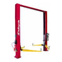
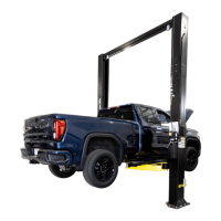
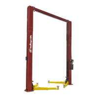
The Challenger Lifts CL10V3-DPC is a two-post, surface-mounted vehicle lift designed for installation, operation, and maintenance in a service bay. This model features a Versymmetric™ design and DUAL PENDANT CONTROL, offering flexibility and ease of use for lifting vehicles up to 10,000 lbs.
The CL10V3-DPC lift is designed to raise and lower vehicles for maintenance and repair. Its Versymmetric™ design allows for both symmetric and asymmetric lifting, accommodating a wide range of vehicle types and sizes. The dual pendant control system provides convenient operation from either side of the lift, enhancing efficiency and safety. The lift operates hydraulically, utilizing a power unit to drive cylinders that raise the carriages and arms. A synchronizing cable system ensures that both columns raise and lower in unison, maintaining a level lift. Safety locks engage automatically as the lift rises, providing secure support for the vehicle at various heights. An overhead limit switch prevents the lift from over-raising and contacting the overhead beam.
The CL10V3-DPC series offers several configurations, denoted by CL10, CL10-2, and CL10-3, which primarily differ in column height and corresponding floor to overhead switch clearance.
| Brand | Challenger Lifts |
|---|---|
| Model | Versymmetric CL10V3-DPC |
| Category | Lifting Systems |
| Language | English |