Do you have a question about the Challenger Lifts Versymmetric VLE10 and is the answer not in the manual?
Calculate clearance based on the full raised height of the lift for safe installation.
Ensure proper concrete floor condition and minimum depth for safe installation.
Lift evaluated for indoor use with specific operating temperature range.
Dedicated circuit with circuit breaker or time delay fuse is necessary.
Read and understand all safety notices and decals for safe operation.
Follow ANSI/ALI standards and wear safety glasses during installation.
List of minimum required tools for lift installation.
Lay out service bay and chalk lines for accurate column placement.
Drill anchor holes and secure columns using anchor bolts with proper shimming.
Install overhead assembly, limit switch, and shutoff bar.
Route and attach synchronizer cables to carriages and sheaves.
Mount power unit, connect hydraulic lines, and fill with approved hydraulic oil.
Install bolt-on hose guide components for column extensions.
Install lock release rod, clevis, knob, and cable assembly for lock pawls.
Lubricate arm pins and install arms, ensuring restraints and stops are secure.
Connect overhead limit switch, power unit, and contactor per wiring diagram.
Clean columns and apply safety and logo decals at specified locations.
Bleed air from cylinders and test hydraulic system for leaks and proper function.
Adjust synchronizing cables for equal tension and simultaneous latch operation.
Adjust cable tension to ensure full disengagement of lock pawls.
Demonstrate lift operation, provide literature, and complete warranty registration.
Understand safety labels, owner duties, and follow basic safety precautions.
Follow basic safety precautions when using garage equipment.
Steps for centering vehicle, positioning arms, and raising lift safely.
Steps for clearing the area, disengaging latches, and lowering the lift.
Actions to take if the lift will not raise or locks will not retract.
| Model | VLE10 |
|---|---|
| Category | Lifting Systems |
| Manufacturer | Challenger Lifts |
| Lifting Capacity | 10, 000 lbs |
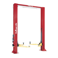
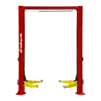
| Lift Type | Versymmetric |
| Voltage | 208-230V |
| Phase | 1 Phase |
| Overall Height | 145 inches |
| Arm Set | 3-Position |