Do you have a question about the Challenger Lifts CL12A and is the answer not in the manual?
Lists essential tools required for the safe and proper installation of the lift.
Guidance on determining the lift's optimal location and orientation within the service bay.
Procedures for preparing lift components before commencing assembly and installation.
Visual guides illustrating hydraulic hose routing based on lift configuration and dimensions.
Table specifying correct hydraulic hose routing for different lift height and width options.
Procedures for adjusting and bleeding the hydraulic system after installation.
Adjusting synchronizing cables for equal tension and simultaneous latch operation.
Adjusting the lock release for proper disengagement and engagement of column locks.
Installing the arm pin keeper mechanism to secure the lift arms.
Steps to verify lift operation, safety features, and hand over documentation to the owner.
Overview of essential safety warnings and decals for safe lift operation.
Defines the duties of owners and employers regarding lift safe use, training, and maintenance.
Critical safety precautions to follow when operating garage equipment.
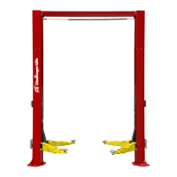
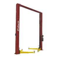
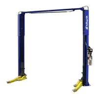
This document describes the installation, operation, and maintenance of a two-post, surface-mounted lift designed for automotive service. The lift is intended for indoor use within a specified ambient temperature range.
The primary function of this device is to safely raise and lower vehicles for maintenance and repair, providing access to the undercarriage. It operates by means of hydraulic cylinders and a synchronizing cable system that ensures both carriages move in unison. The lift incorporates a locking pawl system to secure the carriages at various heights, enhancing safety during operation. A power unit, which can be single-phase or three-phase, drives the hydraulic system. The lift is designed with adjustable height and width configurations to accommodate different service bay layouts and vehicle sizes. An overhead beam connects the two columns, providing structural integrity and housing an overhead limit switch that prevents over-raising of the lift. Arm restraint assemblies are included to secure the vehicle's arms during lifting.
Before using the lift, it is crucial to read the entire manual, including all safety notices and decals. Proper installation is paramount for safe operation, and the manual provides detailed instructions for this process.
The installation process begins with site preparation, ensuring adequate vertical clearance and a suitable concrete floor. The concrete must meet minimum depth, strength, and curing requirements, and the installation area should be level. Anchor bolts are used to secure the columns to the floor, with specific instructions for drilling, cleaning, and torquing the bolts. Shims are provided to plumb the columns, ensuring they are perfectly vertical.
The lift columns are assembled with extensions to achieve the desired height and width configuration. The lower sheave bracket position is determined by these choices, influencing the synchronizer cable routing. The synchronizer cables are critical for maintaining level lifting and are routed through the carriages and over upper sheaves. Hydraulic hoses are routed and connected, with specific instructions for proper fitting seal to prevent leaks. The power unit is mounted to the power column, and electrical connections are made according to the provided wiring diagrams, ensuring a dedicated circuit with appropriate circuit protection.
Locking pawl components are installed on both power and idler columns, and the lock release cables are routed and adjusted to ensure proper engagement and disengagement of the locks. Arm restraint assemblies, including inner arm gears, are installed on the carriages and adjusted to allow free rotation of the arms when the lift is fully lowered. Adapter racks are also installed on the columns for convenient storage of stack adapters.
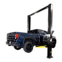
To operate the lift, the vehicle must be centered between the columns, ensuring its center of gravity is midway between the adapters. The lifting arms and adapters are positioned to contact the vehicle's manufacturer-recommended lift points simultaneously. It is critical that the vehicle remains level throughout the lifting process. The raise button is pressed to lift the vehicle, and its stability is tested once the wheels are off the ground. If unstable, the lift is lowered, and the arms are readjusted. The lift should be raised to a height a few inches above the desired working height, then lowered until the latches on both columns engage, securing the vehicle in the locks. Always lower the lift into the locks before working underneath the vehicle, and use safety stands when removing or installing heavy components.
To lower the vehicle, ensure the area beneath is clear. The raise button is pressed to free the latches, then the lock release lever is pulled down to disengage the locks. The lowering valve handle is depressed to lower the vehicle until the carriages stop against the base plate. The extension arms are then retracted, and the lift is parked.
Regular maintenance and inspection are essential for safe and reliable lift operation. The manual outlines a routine maintenance program, emphasizing that only qualified personnel should perform maintenance tasks, following lockout/tagout instructions.
Daily tasks include keeping lift components clean, checking for loose or broken parts, inspecting the hydraulic system for fluid leaks, and checking adapters for damage or excessive wear. The lock release activation should also be checked to ensure proper engagement and return to position.
Weekly checks involve inspecting synchronizer cables and sheaves for wear and adjusting synchronizer cable tension as needed to ensure both carriages are firmly sitting on the locks.
Monthly maintenance includes torquing concrete anchor bolts to specified values and visually inspecting the concrete floor for cracks or spalling around the base plates. The overhead shutoff switch should be tested by operating the overhead shutoff bar while raising the lift, verifying that the power unit motor stops. Carriage slide tracks should be lubricated with heavy viscous grease at all four corners of both columns.
The manual also provides instructions for bleeding air from the hydraulic system and pressure testing it to ensure it is leak-free. It specifies the type of hydraulic oil to be used and warns against using oils with detergents. All safety, warning, and caution labels must be replaced if missing or damaged. In case of any problems, the local service representative should be contacted. The owner/employer is responsible for ensuring operators are trained, establishing inspection and maintenance procedures, maintaining records, and displaying operating instructions and safety manuals in a conspicuous location.
| Lifting Capacity | 12, 000 lbs |
|---|---|
| Rise Time | 45 seconds |
| Voltage | 220V |
| Max Lift Height | 82 inches |
| Motor | 2 HP |
| Power Requirements | 220V |