7 . ACCESSORIES AND OPTIONS
7.70
Challenger MT500B EU
However, for the DUAL CONTROL to operate correctly,
the front linkage position sensor must be calibrated.
IMPORTANT: This operation must be performed on
first use, or as soon as work is carried out on the front
linkage position sensor.
NOTE: If a memory is active, the calibration is stored in
this memory.
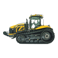
To carry out calibration, press the key
«
6
when the window
(Fig. 159) is open. The window (Fig. 161) is displayed.
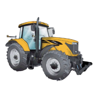
Conditions required for calibration:
- Joystick control unlocked and front linkage set approxi-
mately at mid- travel.
- rear linkage control unlocked and in lowering position (7
Fig. 162),
- engine speed at 1500 rpm,
- rear linkage height / depth setting control set to
between 3 and 4 (8 Fig. 162).
IMPORTANT: For efficient calibration, the front linkage
must be able to move from its highest position to its
lowest position. For this purpose, perform the calibra-
tion without any front implements.
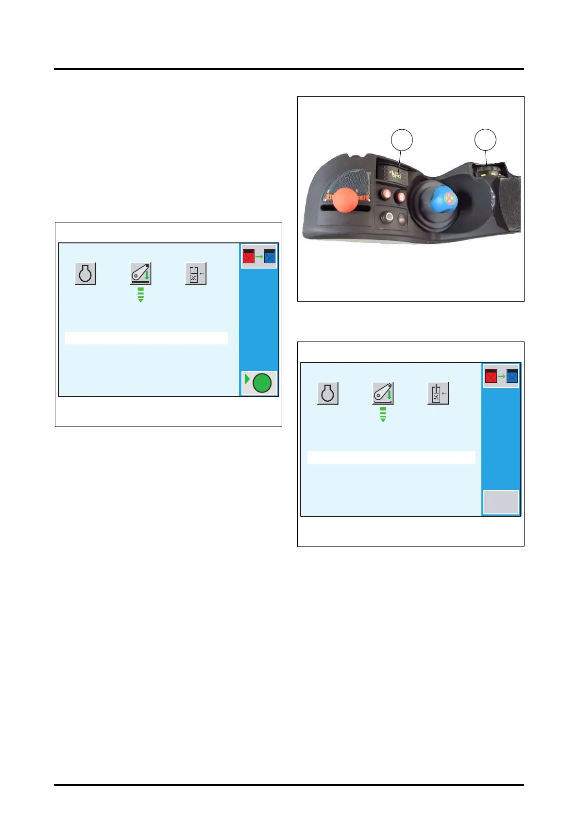
• Press the key
«
6
(GO). Calibration starts and a new win-
dow is displayed (Fig. 163).
During calibration, the front linkage is lifted and lowered
several times. Then, as soon as calibration is complete, the
window (Fig. 161) is displayed again.
DANGER: Ensure that no one can enter the front link-
age operating area throughout the calibration process.
IMPORTANT: In an emergency, press the key
«
6
(STOP)
to stop calibration.
When sensor calibration is complete, a new window is dis-
played (Fig. 164). This indicates the values read by the DA-
TATRONIC required by the service engineer.
1500
3<<..<<4
<<6=OK ESC=EXIT
GO
CALIBRATION MODE
RPM
Z3A-958-08-04-B
Fig. 161
Fig. 162
7
8
Z3A-706-07-04
1500
3<<..<<4
CALIBRATION EN COURS ...
CALIBRATION MODE
RPM
Sensor = 20
STOP
Z3A-1013-08-04-B
Fig. 163
 Loading...