7 . ACCESSORIES AND OPTIONS
7.89
Challenger MT500B EU
7
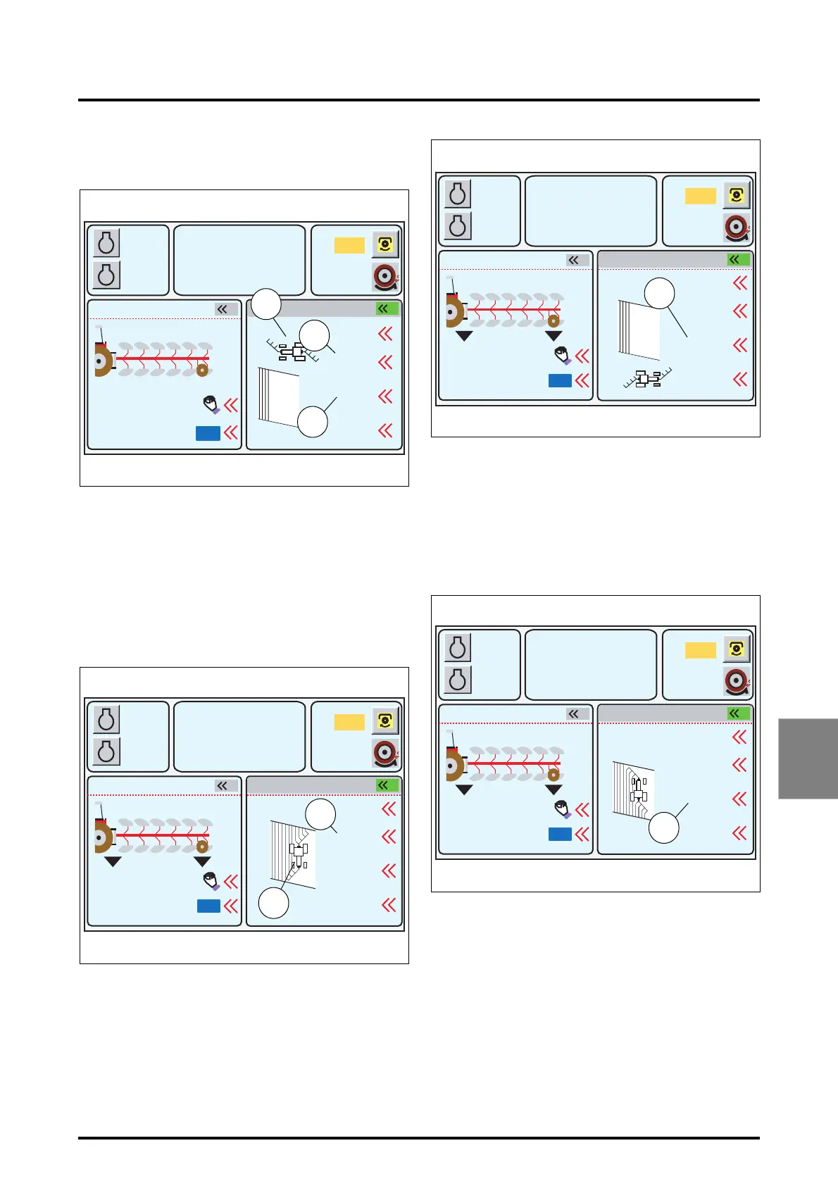
On furrow start (outward run):
The tractor icon on display is in transport position (81 Fig.
220).
The lengths (82 and 83 Fig. 220) are positive. Indeed, in this
example, the furrow start and end lengths must be
extended to perform a straight furrow start and end.
As soon as the linkage Lowering control is actuated, the
tractor icon is positioned in the centre of the field (working
position) (84 Fig. 221).
When the tractor is in working position, the positive length
become negative (85 Fig. 221). This is because when the
tractor icon moves up the window, i.e. on its return run, the
furrow end length should be negative.
On furrow end (outward run):
As soon as the linkage lifting control is actuated, the tractor
icon is positioned at the bottom of the field (Fig. 222). The
furrow end length becomes negative (86 Fig. 222). This is
because when the tractor icon moves up the window, i.e.
on its return run, the furrow start length should be nega-
tive.
On furrow start (return run):
As soon as the linkage lowering control is actuated, the
tractor icon is positioned in the centre of the field (working
position) (Fig. 223).
When the tractor icon is in working position, the negative
length become positive (87 Fig. 223). This is because when
the tractor icon moves down the window, i.e. on its next
run, the furrow end length should be negative.
A
B
1000
2000
790
5.3
10% M
5%
540
1
2000
1.4
3.2
Reset
Syncr
2
ON
Z3A-1369-12-04
Fig. 220
REAR DUAL CTRL POINTS
m
m
RPM
KPH
81
82
83
A
B
1
2
1000
2000
790
5.3
10% M
5%
540
2000
5 % 73 %
-1.4
3.2
Reset
ON
Syncr
Z3A-1024-09-04-B
Fig. 221
m
m
REAR DUAL CTRL POINTS
RPM
KPH
85
84
A
B
1
2
1000
2000
790
5.3
10% M
5%
540
2000
5 % 73 %
-1.4
-3.2
Reset
ON
Syncr
Z3A-811-08-04-B
Fig. 222
REAR DUAL CTRL
POINTS
m
m
RPM
KPH
86
A
B
1
2
1000
2000
790
5.3
10% M
5%
540
2000
5 % 73 %
-1.4
3.2
Reset
ON
Syncr
Z3A-812-08-04-B
Fig. 223
REAR DUAL CTRL POINTS
m
m
RPM
KPH
87
 Loading...