7 . ACCESSORIES AND OPTIONS
7.75
Challenger MT500B EU
7
To return to the window (Fig. 175), press the key «
5
when
the window (Fig. 177) is open and the icon (22 Fig. 177) is
green or in reverse video on b/w screens.
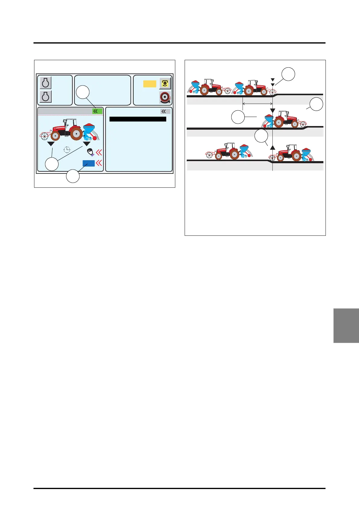
7.13.2.9 - Working operation
Furrow start:
When the tractor is at the start of a furrow, activate the rear
linkage lowering control as soon as the tractor front imple-
ment reaches mark Y (26 Fig. 178). The front implement
lowers to below the set working depth because the tractor
front is ballasted (front linkage extra-lowering). When dis-
tance X has been travelled, the rear linkage lowers auto-
matically (27 Fig. 178). The back of the tractor is now
ballasted. Thus the front linkage raises slightly to working
position (28 Fig. 178).
Furrow end:
At the end of a furrow, activate the rear linkage lifting con-
trol when the front implement reaches mark Y (29 Fig.
178). The front implement lifts. When distance X has been
travelled, the rear linkage is automatically activated to lift
the implement.
NOTE: For pointed fields, however, the POINTS menu
must be used to optimise the operation of the DUAL
CONTROL (see paragraph 7.8.5).
IMPORTANT: If the linkage high and low stops are mod-
ified during work, they are not stored in the
DATATRONIC active memory. To memorise them, see
paragraph 7.8.2.2.
A
B
1000
2000
790
5.3
10% M
5%
540
2
2000
5 % 73 %
1
ON
Z3A-1314-11-04-B
Fig. 177
GEARBOX SETTINGS
ACTIVE MEMORY
HEADLAND
POINTS
EHS VALVES 5-6
EHS VALVES 1-4
FRONT DUAL CTRL
RPM
KPH
25
22
24
Y
X
Z3A-946-08-04-B
Fig. 178
26
27
28
LEGEND:
26. Lowering the front linkage below working position
27. Lowering the rear linkage into working position
28. Lifting the front linkage into working position
29. Lifting of the front linkage
29
 Loading...